


Considerations When Using Cylinder Lenses
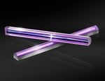
Cylinder lenses are similar to spherical lenses in the sense that they use curved surfaces to converge or diverge light, but they have optical power in only one dimension and will not affect light in the perpendicular dimension. This is impossible to accomplish using spherical lenses as light will focus or diverge uniformly in a rotationally symmetric manner. Cylinder lenses play an important role in the manipulation and shaping of laser light and are used for forming laser light sheets and circularizing elliptical beams. Due to the asymmetric nature of cylinder lenses and the specialized manufacturing processes required, it is important that the centration, wedge, and axial twist are specified and properly controlled.
For this reason, cylinder lenses require specialized equipment and skills to manufacture, along with requiring a unique coordinate system to effectively reference features of a lens. Two orthogonal directions define the reference system: the power direction and the non-power direction. The first direction is called the “power direction” because it runs along the curved length of the lens, and is the only axis with optical power (Figure 1). The second direction is called the “non-power direction” because it runs along the length of the lens without any optical power. The length of the cylinder lens along the non-power direction can extend without affecting the optical power of the lens. Cylinder lenses can have a variety of form factors including rectangular, square, circular, and elliptical shapes.
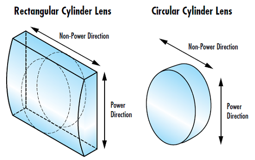
Figure 1: Power and non-power directions in both rectangular and circular cylinder lenses
Errors, Aberrations, and Specifications
No manufacturing process is free of imperfections, and cylinder lens manufacturing is no exception, which makes small amounts of geometric errors unavoidable. Misalignment during the polishing process could lead to a number of mechanical errors specific to cylinder lenses that can cause optical aberrations and negatively impact performance. Therefore, these errors must be tightly controlled to guarantee the performance of the lens. These errors are defined with respect to geometric datums including the planar side of the lens and the edges of the lens.
Wedge
In an ideal cylinder, the planar side of the lens is parallel to the cylinder axis. Angular deviation between the planar side of the lens and the cylinder axis is known as the wedge, which is typically measured in arcmin (Figure 2). This angle is determined by measuring the two end thicknesses of the lens and calculating the angle between them. Wedge leads to an image shift in the non-power direction, just like wedge in a window.
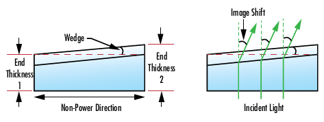
Figure 2: Example of an exaggerated wedge caused by end thickness difference in the non-power direction of a cylinder lens
Centration
The optical axis of the curved surface is parallel to the edges of the lens in an ideal cylinder lens (Figure 3). Similar to decenter of a surface with optical power in a spherical optic, the centration error of a cylinder lens is an angular deviation of the optical axis with respect to the edges of the lens. This centration angle (α) causes the optical and mechanical axes of the lens to no longer be collinear, leading to beam deviation. If the edges of the lens are used as a mounting reference, this error can make optical alignment very difficult. However, if the edges of the lens is not relied on for mounting reference, it is possible to remove this error by decentering the lens in the correct direction. The larger the diameter of a cylinder lens, the larger the associated edge thickness difference for a given centration angle.
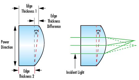
Figure 3: Example of centration error caused by an edge thickness difference in the power direction of a cylinder lens
Axial Twist
Axial twist is an angular deviation between the cylinder axis and the edges of a lens. Axial twist represents a rotation of the powered surface of the cylinder lens with respect to the outer dimensions, leading to a rotation of the image about the optical plane. This is especially detrimental to an application when rectangular elements are secured by their outer dimensions (Figure 4). Rotating a cylinder lens to realign the cylinder axis can counteract axial twist.
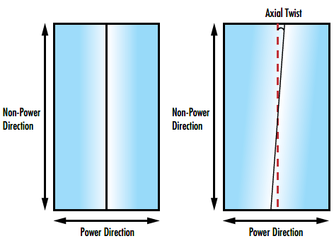
Figure 4: Example of axial twist in a cylinder lens
Applications
Cylinder lenses are most commonly used in laser beam shaping to correct an asymmetric beam, create a line, or generate a light sheet. Modern scientific methods such as Particle Image Velocimetry (PIV) and Laser Induced Fluorescence (LIF) often require a thin laser line or an even laser light sheet. Structured laser light is also an important tool for scanning, measurement, and alignment applications. With low cost laser diodes now readily available, another common application is simply circularizing the elliptical output from a diode to create a collimated and symmetric beam.
Forming a Light Sheet
A light sheet is a beam that diverges in both the X and the Y axes. Light sheets include a rectangular field orthogonal to the optical axis, expanding as the propagation distance increases. A laser line generated using a cylinder lens can also be considered a light sheet, although the sheet has a triangular shape and extends along the optical axis.
To create a true laser light sheet with two diverging axes, a pair of convex or concave cylinder lenses orthogonal to each other are required (Figure 5). Each lens acts on a different axis and the combination of both lenses produces a diverging sheet of light.
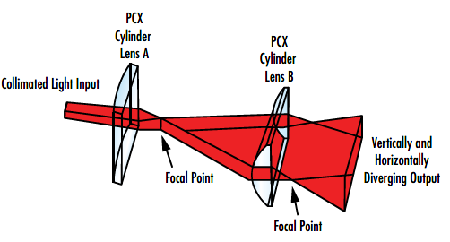
Figure 5: Example of orthogonal cylinder lenses used to generate a rectangular light sheet
Circularizing a Beam
A laser diode with no collimating optics will diverge in an asymmetrical pattern. A spherical optic cannot be used to produce a circular collimated beam as the lens acts on both axes at the same time, maintaining the original asymmetry. An orthogonal pair of cylinder lenses allows each axis to be treated separately.
To achieve a symmetrical output beam, the ratio of the focal lengths of the two cylinder lenses should match the ratio of the X and Y beam divergences. Just as with standard collimation, the diode is placed at the focal point of both lenses and the separation between the lenses is therefore equal to the difference of their focal lengths (Figure 6).
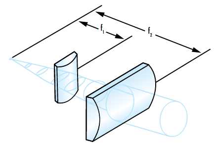
Figure 6: Example of circularizing an elliptical beam using cylinder lenses
Laser diodes may have a very large divergence, which can be a challenge when trying to collimate because divergence has a direct effect on the allowable length of the system, as well as the required sizes of the lenses. As the relative positions of each component are fairly fixed due to their focal length, it is possible to calculate the maximum beam width (d) at each lens using the focal length of the lens (f) and the divergence angle (θ) of the axis it is collimating. The clear aperture of each lens must then be larger than the corresponding maximum beam width.
Cylinder Lenses from Edmund Optics®
Edmund Optics offers a wide range of cylinder lenses including plano-convex, plano-concave, achromatic, and acylindrical versions with a variety of substrates and coatings.

More Resources
- Cylinder Lenses
- What Are Cylinder Lenses? Application Note
- Why Choose an Achromatic Cylinder Lens?
- Laser Optics Lab Video Series


or view regional numbers
QUOTE TOOL
enter stock numbers to begin
Copyright 2023 | Edmund Optics, Ltd Unit 1, Opus Avenue, Nether Poppleton, York, YO26 6BL, UK
California Consumer Privacy Act (CCPA): Do Not Sell or Share My Personal Information
California Transparency in Supply Chains Act