


How to Design your own Beam Expander Using Stock Optics

Beam expanders, commonly used in interferometry, remote sensing, laser materials processing and laser scanning applications, accept collimated light into the system and expand it into a larger collimated beam as its output. While a variety of off-the-shelf beam expanders are available, occasionally these standard beam expanders may not meet your application needs. Designing your own beam expander provides the flexibility to design to your exact application specifications, and using stock optics reduces your time from design to prototype to days. Additionally, the use of stock optics allows almost instantaneous scaling into volume when you are ready for production.
Design Requirements
Some requirements to consider before you begin choosing parts to build your laser beam expander are system cost, mechanical constraints, and system performance. It is recommended to assign the priority level of each requirement before beginning. While listing your requirements, you could find that your specific application may have more or less to consider than those listed below.
When considering system costs, it’s important to realize the tradeoff between cost and performance. The cost of uncoated optics, potential optical coatings, and the mounts for the optics will be influenced by quantity, chosen materials, and precision. N-BK7 is often an ideal material because of its broad wavelength range and low cost, whereas Fused Silica is often used for more demanding applications because of its low coefficient of thermal expansion and high laser damage threshold. For a single laser beam expander that works for a variety of wavelengths, chromatic effects should be considered as well. For example, N-SF11 and N-BK7 can create an achromatic solution for a small range of wavelengths. Be sure to check the material when deciding if a lens is a good candidate to use for your laser beam expander.
Often, a laser beam expander needs to fit within a constrained area, limiting both the overall diameter and length of the system. It’s important to remember that larger beams require larger laser beam expanders, which require larger (and more costly) optics and more metal for the housing.
Additionally, some designs may require divergence adjustment. Rotating divergence adjustment, such as a threaded focusing tube, are a popular choice because of their low cost. However, these mechanisms rotate the optics when translating them, creating the potential for wander within the output beam. Sliding mechanisms, such as a helicoid barrel, translate the optics perpendicular to the optical axis without rotating them, minimizing beam wander, but increasing system cost.
Before designing your laser beam expander, be aware of system performance requirements. At a minimum, a laser beam expander design requires a specific wavelength or wavelength range, a specific input beam diameter, and a minimum acceptable transmission. Larger wavelength ranges are more difficult to design, adding complexity and cost, whereas smaller input apertures are easier over which to maintain performance requirements. Overall transmission is heavily influenced by the selection of appropriate anti-reflection coatings; uncoated optics reduce cost, but also lower overall transmission (and potentially create harmful reflections in the laser beam expander), whereas a coating as simple as a single layer MgF2 can ensure transmission of 90% or better. Beam quality is often specified as wavefront distortion, and a value of less than λ/4 peak-to-valley (PV) is typically considered to be diffraction limited.
It is difficult to adjust one parameter without affecting other parameters. For example, selecting a different set of lenses to improve wavefront quality might increase system cost or impact the overall system size. It should also be noted that increasing the input beam diameter has an exponential effect on the quality of the transmitted wavefront, and for this reason, bigger input beams are significantly harder to design for. Be cautious of the tolerance of the components used – the tighter the tolerances, the more expensive it will be to make the system.
Keplerian vs. Galilean Beam Expander Designs
Designing a laser beam expander from off-the-shelf lenses can drastically reduce lead time and speed up the design cycle. By utilizing Zemax’s lens catalog, stock lenses can be easily selected and spacing can be adjusted for your design criteria. With Edmund Optics’ industry-leading selection of off-the-shelf lenses, either Keplerian or Galilean designs are possible. Keplerian designs will have a longer system length with an internal focus, whereas Galilean designs will be shorter and not have the internal focal point.
Keplerian laser beam expanders have an intermediate focus plane in the design. This presents both advantages and disadvantages over Galilean designs. At high powers, the focus plane is a significant disadvantage as air can become ionized, reducing transmitted energy and creating potentially harmful energy levels. At lower powers, the focus plane can be used as an ideal position for a spatial filter, allowing for easy and effective beam cleanup. Finally, Galilean designs are typically shorter than Keplarian ones for the same magnification.
General Galilean Beam Expander Design Considerations
The magnification of a Galilean beam expander is determined by the following equations.
Where $ \small{f_1} $ is the focal length of the positive lens and $ \small{f_2} $ is the focal length of the negative lens. Designing using stock optics is as simple as selecting a positive and negative lens that meets your magnification requirements (Equation 1) without exceeding your system length requirements (Equation 2). As illustrated further these equations are first-order equations, and lens thickness and focus optimization will cause slight deviations from these ideal values.
Lens clear aperture also needs to be taken into account during the selection, as the negative lens must be large enough to accommodate the input beam, while the positive lens must be large enough to output the magnified beam without vignetting.
For example, in a 5X system with a 3mm input beam, a 10mm diameter positive lens will cause vignetting since the output beam will be 15mm in diameter. A large catalog of in-stock lenses should provide a sufficient selection of diameters and focal lengths to meet most magnification requirements.
Designing a 5X Galilean Beam Expander
Consider an application where you need to design a 5X beam expander with a system length of no more than 75mm. A two singlet Galilean, design would allow each of the following possible stock lens combinations: -6mm and 30mm, -9mm and 45mm, -12mm and 60mm, and -15mm and 75mm. Note that -25mm/125mm, -20mm/100mm combinations will not meet the requirement of the system length of less than 75mm. While a -18mm/90mm combination may work within the requirement, it’s exceedingly likely that the metal of the system as well as the actual lens thicknesses will increase the length beyond the stated requirements.
In a two singlet Galilean beam expander design, a good rule of thumb is that wavefront quality will increase with increasing optical track. In other words, a -20mm and 100mm lens combination will have a much better wavefront than that of a -6mm and 30mm. Also, using lenses with plano surfaces (such as plano-convex or plano-concave) rather than lenses with curvature on both surfaces will improve wavefront quality. If using plano- lenses and a Galilean layout, orienting the plano surface towards the input beam tends to improve the wavefront quality by balancing out spherical aberration. However, if using high-power lasers, reflections from the first plano surface, even if anti-reflection coated, could damage your laser.
The interactive simulation below allows you to create a beam expander out of two spherical lenses.
To begin, click the blue Simulation button in the upper-left corner. Next:
Click on either of the two detectors to see how the beam diameter differs before and after the beam expander
Click on either of the two lenses to see their focal lengths and even swap them out for different lenses
Click on the second lens to change its position. The spacing between both lenses is displayed on the screen
Click on the laser to change its wavelength
Rotate and zoom in on the screen using your mouse and/or mousepad
After making changes, re-run the simulation by clicking the Simulation button again to see updated detector readings
Selecting the Right Lenses
Table 1 shows which lenses to select in order to create a 532nm Keplerian beam expander of a given magnification. The same lens sizes and focal lengths can be used with different coatings to tailor the beam expander for different wavelengths, and the same focal length ratios will work for constructing a Galilean beam expander. One of the two lenses will just have a negative focal length instead of a positive one.
| 5mm Diameter | 12mm Diameter | 25mm Diameter | 50mm Diameter | ||||||||||||||||||||||
| Lens 2 | #34-083 | #34-084 | #34-085 | #34-086 | #34-087 | #34-088 | #34-089 | #34-090 | #34-091 | #34-092 | #34-093 | #34-094 | #34-095 | #34-096 | #34-097 | #34-098 | #34-099 | #34-100 | #34-101 | #34-102 | #34-103 | #34-104 | #34-105 | ||
| Lens 1 | FL (mm) | 10 | 15 | 20 | 25 | 18 | 25 | 30 | 36 | 50 | 100 | 38 | 50 | 60 | 75 | 100 | 125 | 150 | 200 | 75 | 100 | 150 | 200 | 250 | |
| 5mm Diameter | #34-083 | 10 | 1.0 | 1.5 | 2.0 | 2.5 | 1.8 | 2.5 | 3.0 | 3.6 | 5.0 | 10.0 | 3.8 | 5.0 | 6.0 | 7.5 | 10.0 | 12.5 | 15.0 | 20.0 | 7.5 | 10.0 | 15.0 | 20.0 | 25.0 |
| #34-084 | 15 | 0.7 | 1.0 | 1.3 | 1.7 | 1.2 | 1.7 | 2.0 | 2.4 | 3.3 | 6.7 | 2.5 | 3.3 | 4.0 | 5.0 | 6.7 | 8.3 | 10.0 | 13.3 | 5.0 | 6.7 | 10.0 | 13.3 | 16.7 | |
| #34-085 | 20 | 0.5 | 0.8 | 1.0 | 1.2 | 0.9 | 1.2 | 1.5 | 1.8 | 2.5 | 5.0 | 1.9 | 2.5 | 3.0 | 3.8 | 5.0 | 6.2 | 7.5 | 10.0 | 3.8 | 5.0 | 7.5 | 10.0 | 12.5 | |
| #34-086 | 25 | 0.4 | 0.6 | 0.8 | 1.0 | 0.7 | 1.0 | 1.2 | 1.4 | 2.0 | 4.0 | 1.5 | 2.0 | 2.4 | 3.0 | 4.0 | 5.0 | 6.0 | 8.0 | 3.0 | 4.0 | 6.0 | 8.0 | 10.0 | |
| 12mm Diameter | #34-087 | 18 | 0.6 | 0.8 | 1.1 | 1.4 | 1.0 | 1.4 | 1.7 | 2.0 | 2.8 | 5.6 | 2.1 | 2.8 | 3.3 | 4.2 | 5.6 | 6.9 | 8.3 | 11.1 | 4.2 | 5.6 | 8.3 | 11.1 | 13.9 |
| #34-088 | 25 | 0.4 | 0.6 | 0.8 | 1.0 | 0.7 | 1.0 | 1.2 | 1.4 | 2.0 | 4.0 | 1.5 | 2.0 | 2.4 | 3.0 | 4.0 | 5.0 | 6.0 | 8.0 | 3.0 | 4.0 | 6.0 | 8.0 | 10.0 | |
| #34-089 | 30 | 0.3 | 0.5 | 0.7 | 0.8 | 0.6 | 0.8 | 1.0 | 1.2 | 1.7 | 3.3 | 1.3 | 1.7 | 2.0 | 2.5 | 3.3 | 4.2 | 5.0 | 6.7 | 2.5 | 3.3 | 5.0 | 6.7 | 8.3 | |
| #34-090 | 36 | 0.3 | 0.4 | 0.6 | 0.7 | 0.5 | 0.7 | 0.8 | 1.0 | 1.4 | 2.8 | 1.1 | 1.4 | 1.7 | 2.1 | 2.8 | 3.5 | 4.2 | 5.6 | 2.1 | 2.8 | 4.2 | 5.6 | 6.9 | |
| #34-091 | 50 | 0.2 | 0.3 | 0.4 | 0.5 | 0.4 | 0.5 | 0.6 | 0.7 | 1.0 | 2.0 | 0.8 | 1.0 | 1.2 | 1.5 | 2.0 | 2.5 | 3.0 | 4.0 | 1.5 | 2.0 | 3.0 | 4.0 | 5.0 | |
| #34-092 | 100 | 0.1 | 0.1 | 0.2 | 0.2 | 0.2 | 0.2 | 0.3 | 0.4 | 0.5 | 1.0 | 0.4 | 0.5 | 0.6 | 0.8 | 1.0 | 1.2 | 1.5 | 2.0 | 0.8 | 1.0 | 1.5 | 2.0 | 2.5 | |
| 25mm Diameter | #34-093 | 38 | 0.3 | 0.4 | 0.5 | 0.7 | 0.5 | 0.7 | 0.8 | 0.9 | 1.3 | 2.6 | 1.0 | 1.3 | 1.6 | 2.0 | 2.6 | 3.3 | 3.9 | 5.3 | 2.0 | 2.6 | 3.9 | 5.3 | 6.6 |
| #34-094 | 50 | 0.2 | 0.3 | 0.4 | 0.5 | 0.4 | 0.5 | 0.6 | 0.7 | 1.0 | 2.0 | 0.8 | 1.0 | 1.2 | 1.5 | 2.0 | 2.5 | 3.0 | 4.0 | 1.5 | 2.0 | 3.0 | 4.0 | 5.0 | |
| #34-095 | 60 | 0.2 | 0.2 | 0.3 | 0.4 | 0.3 | 0.4 | 0.5 | 0.6 | 0.8 | 1.7 | 0.6 | 0.8 | 1.0 | 1.2 | 1.7 | 2.1 | 2.5 | 3.3 | 1.2 | 1.7 | 2.5 | 3.3 | 4.2 | |
| #34-096 | 75 | 0.1 | 0.2 | 0.3 | 0.3 | 0.2 | 0.3 | 0.4 | 0.5 | 0.7 | 1.3 | 0.5 | 0.7 | 0.8 | 1.0 | 1.3 | 1.7 | 2.0 | 2.7 | 1.0 | 1.3 | 2.0 | 2.7 | 3.3 | |
| #34-097 | 100 | 0.1 | 0.1 | 0.2 | 0.2 | 0.2 | 0.2 | 0.3 | 0.4 | 0.5 | 1.0 | 0.4 | 0.5 | 0.6 | 0.8 | 1.0 | 1.2 | 1.5 | 2.0 | 0.8 | 1.0 | 1.5 | 2.0 | 2.5 | |
| #34-098 | 125 | 0.1 | 0.1 | 0.2 | 0.2 | 0.1 | 0.2 | 0.2 | 0.3 | 0.4 | 0.8 | 0.3 | 0.4 | 0.5 | 0.6 | 0.8 | 1.0 | 1.2 | 1.6 | 0.6 | 0.8 | 1.2 | 1.6 | 2.0 | |
| #34-099 | 150 | 0.1 | 0.1 | 0.1 | 0.2 | 0.1 | 0.2 | 0.2 | 0.2 | 0.3 | 0.7 | 0.3 | 0.3 | 0.4 | 0.5 | 0.7 | 0.8 | 1.0 | 1.3 | 0.5 | 0.7 | 1.0 | 1.3 | 1.7 | |
| #34-100 | 200 | 0.1 | 0.1 | 0.1 | 0.1 | 0.1 | 0.1 | 0.1 | 0.2 | 0.2 | 0.5 | 0.2 | 0.2 | 0.3 | 0.4 | 0.5 | 0.6 | 0.8 | 1.0 | 0.4 | 0.5 | 0.8 | 1.0 | 1.2 | |
| 50mm Diameter | #34-101 | 75 | 0.1 | 0.2 | 0.3 | 0.3 | 0.2 | 0.3 | 0.4 | 0.5 | 0.7 | 1.3 | 0.5 | 0.7 | 0.8 | 1.0 | 1.3 | 1.7 | 2.0 | 2.7 | 1.0 | 1.3 | 2.0 | 2.7 | 3.3 |
| #34-102 | 100 | 0.1 | 0.1 | 0.2 | 0.2 | 0.2 | 0.2 | 0.3 | 0.4 | 0.5 | 1.0 | 0.4 | 0.5 | 0.6 | 0.8 | 1.0 | 1.2 | 1.5 | 2.0 | 0.8 | 1.0 | 1.5 | 2.0 | 2.5 | |
| #34-103 | 150 | 0.1 | 0.1 | 0.1 | 0.2 | 0.1 | 0.2 | 0.2 | 0.2 | 0.3 | 0.7 | 0.3 | 0.3 | 0.4 | 0.5 | 0.7 | 0.8 | 1.0 | 1.3 | 0.5 | 0.7 | 1.0 | 1.3 | 1.7 | |
| #34-104 | 200 | 0.1 | 0.1 | 0.1 | 0.1 | 0.1 | 0.1 | 0.1 | 0.2 | 0.2 | 0.5 | 0.2 | 0.2 | 0.3 | 0.4 | 0.5 | 0.6 | 0.8 | 1.0 | 0.4 | 0.5 | 0.8 | 1.0 | 1.2 | |
| #34-105 | 250 | 0.0 | 0.1 | 0.1 | 0.1 | 0.1 | 0.1 | 0.1 | 0.1 | 0.2 | 0.4 | 0.2 | 0.2 | 0.2 | 0.3 | 0.4 | 0.5 | 0.6 | 0.8 | 0.3 | 0.4 | 0.6 | 0.8 | 1.0 | |
Table 1: Selection guide for constructing a 532nm Keplerian beam expander out of off-the-shelf plano-convex lenses from Edmund Optics®.
Optimization using Zemax
We selected a 6mm diameter plano-concave lens with a -12mm focal length (#45-008), and a 25mm diameter plano-convex lens with a 60mm focal length (#45-127) as an example for a 5X system. Since we are using stock lenses, the only variable we assign is the distance between two lenses: the thickness of surface 3. This is shown in Figure 1, which is the Zemax lens data editor. Figure 2 shows the lens layout of the beam expander in afocal mode.
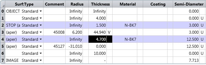
Figure 1: Lens data editor

Figure 2: Beam expander layout
The aperture value in Zemax must be set to the input beam diameter over which you want to optimize your design. In this example, we optimized for 3mm input beam and the output beam will be 15mm. While this is the design input beam diameter, the maximum input diameter is limited by the clear aperture of the front lens. We also assume the input beam is Gaussian, and that we are mounting the beam expander directly to the laser, simplifying the angle of incidence to 0 degrees. Finally, we assumed the laser was a Helium-Neon (HeNe) design and optimized for a design wavelength of 632.8nm.
Since beam expanders are afocal systems, make sure “afocal image space” is checked in the Zemax lens data editor. This will change the units of the metrics to be angular rather than distances. Afocal systems don’t have an effective focal length and thus provide no net convergence or divergence of the incident light beam. Beam expanders and camera zoom lenses are common examples of afocal systems.
Figure 3 shows the Zemax merit function editor. This merit function is a fairly simple one, which can be used as a base for all afocal systems. The operands used are explained in more detail below.
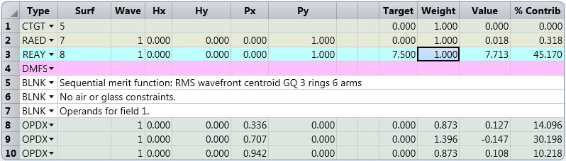
Figure 3: Merit Function Editor
- RAED operand optimizes the real ray angle normal to the surface and we added a dummy surface after the last surface of the positive lens, which in our case is surface 7. We want the output beam to be collimated, meaning the angle normal to the vertical dummy surface should be as small as possible because if it is 0 then the system is truly afocal.
- REAY operand checks the real ray height at a certain surface. We have a zero weight REAY operand in the merit function; they measure the real ray height at first and last surface of the system which is the size of the input and output beam size. Note that the operand measures radii instead of diameter.
- We use the default merit function to optimize for the RMS wavefront error.
After optimization, the system should be diffraction-limited or close to it, as shown in Figures 4 and 5, which show the spot size and wavefront. If the system isn’t as intended, a number of factors should be considered. Was the wavelength of light compatible with the chosen glass material (for instance, N-BK7 won’t transmit 266nm light)? Is the spacing between the two lenses set to be approximately the sum of their focal lengths? Is the beam diameter too large for the chosen front lens? Try making those changes and re-optimizing, to get a similar result to what’s shown.

Figure 4: Spot Size
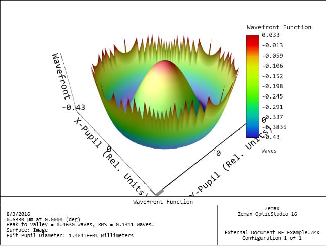
Figure 5: Wavefront 3D map
We have shown that it is possible to rapidly design a 5X beam expander for a 3mm diameter, 632.8nm laser beam. The selected optics are available in stock and could be ordered to immediately prototype the system. When using the approach of stock optics for rapid design, an optical component supplier that has a wide variety of optics available is essential for rapid development. Edmund Optics’ industry-leading selection of stock optics is typically available for next-day delivery, providing the components needed to support a rapid prototyping environment. Once prototyping is complete, stock optics can be used to seamlessly scale into volume with minimal delay and inventory requirements.
Looking to learn about optics and optical design?
Learn the basics of optics needed to begin designing optical systems in this educational, online Fundamentals of Optics course co-created by Edmund Optics and Zemax. It does not require any previous knowledge in the field of optics.
Animation powered by 3DOptix.


or view regional numbers
QUOTE TOOL
enter stock numbers to begin
Copyright 2023 | Edmund Optics, Ltd Unit 1, Opus Avenue, Nether Poppleton, York, YO26 6BL, UK
California Consumer Privacy Act (CCPA): Do Not Sell or Share My Personal Information
California Transparency in Supply Chains Act