Engineers are available to assist.

|
|
Passive Compensation for Thermal Defocus |
|
|
No Additional Refocusing Needed |
|
|
Reduces Harmful Effects from Shock & Vibration |
|
|
Large Sensor Coverage Up to 1.1” |
Matter expands as its temperature increases and shrinks as its temperature decreases. How much a material changes dimensions is related to its coefficient of thermal expansion (CTE) and whether the material is isotropic or anisotropic. The refractive index of transparent materials also changes with temperature. These thermal phenomena present a challenge for manufacturers and imaging system integrators that require temperature-dynamic, robust machine vision systems for applications in environments with dramatic temperature changes. Because materials expand and contract at different rates, a system with both metal and glass presents even more challenges. Materials such as metals and plastics have CTE values 10 to 100 times the CTE values of the optical glass materials packaged within the optical systems.

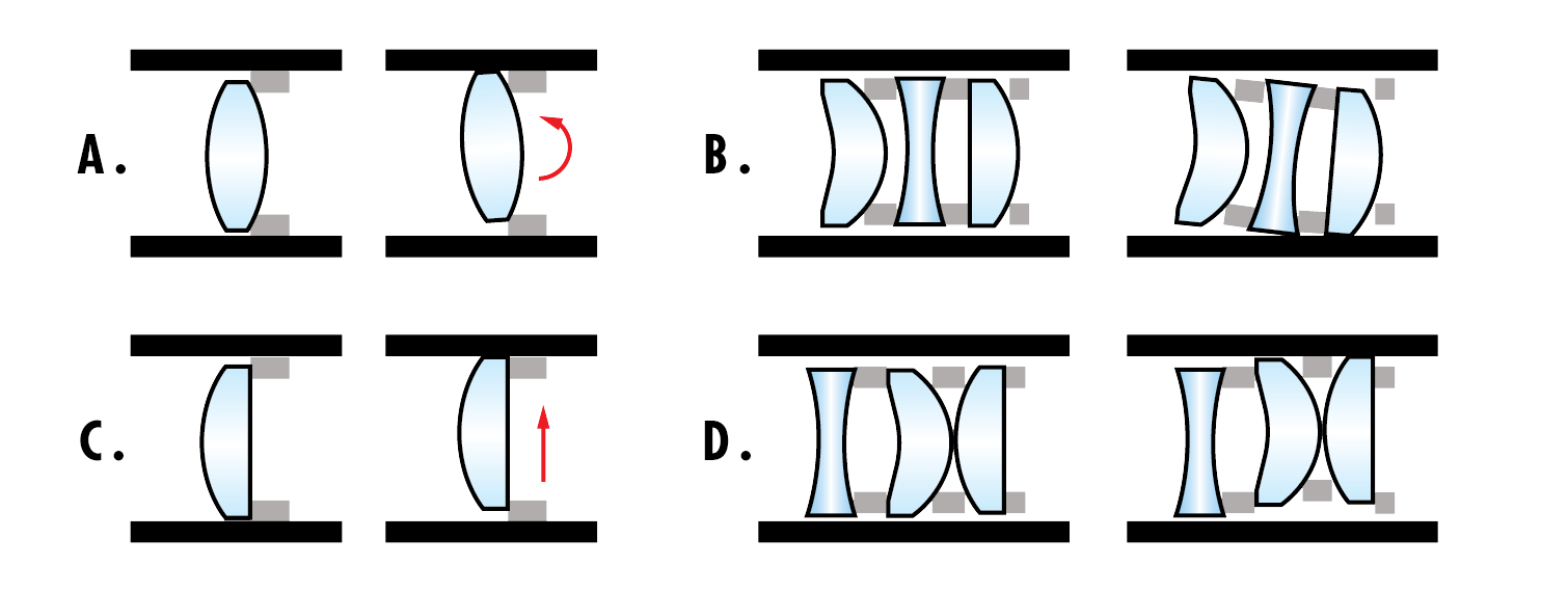
The CTE difference may not matter much if the components are small in size, or if the operational temperature variation is small. Systems having optical elements 25mm in diameter or larger, held in lens barrels with close fits of 10-15 microns of total clearance, can constrict the optics significantly at low temperatures. The reduced diameter of the lens barrel can be capable of applying sufficient stress upon the internal lens elements to fracture them or create edge chips. Conversely, rising temperature can increase the size of the bore gap and exacerbate roll and decenter opportunity of a single lens or coupled lens elements (Figure 2).
The refractive index of a material is the ratio of the speed of light as it travels through a material medium and the speed of light in a vacuum. The temperature coefficient of refractive index is related to how much this ratio changes with temperature. For more information on this coefficient, see Thermal Properties of Optical Substrates.
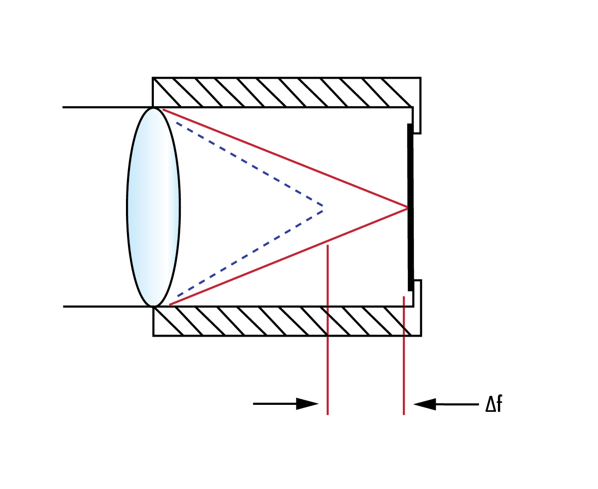
Thermal defocus is directly related to both the change in refractive index and changing material dimensions over the operational temperature range of a lens system. As an example, a heated lens barrel will expand and separate the vertex-to-vertex spacing of the elements, allowing for some decenter or roll, as described. This will cause the index of refraction of the glass materials to change, all combining to affect the resultant focus position of the lens system as the temperature changes in the use case (Figure 3).
Athermalization to minimize focal length change over temperature can be achieved actively or passively. These terms refer to the end user and the amount of work required to use the component in the environment.
Active athermalization can involve the use of additional support hardware that may either “actively” compensate or correct the focus of the lens system, or provide heating or cooling capability to maintain the lens system at a design focal length. Both of these examples require some sort of feedback control to the active system to stabilize the optics at the desired system focus position, or temperature set point, respectively.
While active athermalization makes use of less exotic optical materials and is more robust for use in application environments with larger operating temperature ranges, this type of athermalization can be bulkier and more costly to implement.
Passive athermalization is achieved by exploiting the CTE difference of materials, and building them into the design of the optical system to compensate for both the refractive index and dimensional changes. By combining different materials, focal length can be fixed as temperature changes without the need for additional user intervention or layers of electromechanical support. Because there are fewer technical components, passive athermalization produces products that are typically better for space-constrained applications. Unfortunately, not all optical designs can be passively athermalized; sometimes the required compensation simply cannot be passively achieved within the design volume.
Athermal imaging lenses may be manufactured in either of the two varieties mentioned above. However, the TECHSPEC® Athermal Imaging Lenses, designed by Edmund Optics® and Ruda Cardinal and manufactured by Edmund Optics, are passively athermalized in addition to being industrially ruggedized to protect from lens damage from shock and vibration (Figure 4).


An example lens is shown below in Figure 5 that has been designed to maintain MTF over a 60◦C operational temperature range, making it suitable for a wide range of applications.

 How do I know if an imaging lens is athermalized?
Can an optical system have both active and passive athermalization?
How do I know if an imaging lens is athermalized?
Can an optical system have both active and passive athermalization?
Yes, an optical system can have both forms of athermalization depending on the necessary operating temperature range.
How can temperature negatively affect my operating system?
Temperature changes or operating outside of the operating temperature ranges can cause a number of types of damage to an imaging lens. Both increasing or decreasing temperatures can change the point of focus and can cause elements to roll, decenter, or shift, whereas decreasing temperature can cause internal elements to chip, break, or shatter.
Can my lens system have multiple types of ruggedization?
While it can be difficult to find a stock solution that is ruggedized for several different types of harsh environmental factors, imaging lenses can be designed with these in mind. The TECHSPEC Athermal lenses have been industrial ruggedized to minimize the effects of shock and vibration. Contact us to learn about other custom ruggedization solutions.


or view regional numbers
QUOTE TOOL
enter stock numbers to begin
Copyright 2025 | Edmund Optics BV, De Maas 22B, 5684 PL Best, The Netherlands
California Consumer Privacy Acts (CCPA): Do Not Sell or Share My Personal Information
California Transparency in Supply Chains Act
This content may include material that has been generated or modified using artificial intelligence (AI).
The FUTURE Depends On Optics®