


Distortion and Telecentricity
Authors: Gregory Hollows, Nicholas James
This is Section 4.2 of the Imaging Resource Guide.
Another advantage of using telecentric lenses in metrology applications is that telecentric lenses typically have lower distortion values than fixed focal length lenses. Distortion causes the actual position of an object to appear as though it is in a different location, which can further decrease measurement accuracy (see Distortion). For example, Figure 1a shows jumper pins on a circuit board that has been imaged by a fixed focal length lens with high distortion. The distortion, coupled with the parallax error inherent to non-telecentric lenses, makes the pins toward the edge of the image appear as though they are bent toward the center. When looking at the same pins with a telecentric lens, as in Figure 1b, it is apparent that the pins are indeed straight.
While it is true that distortion can be calibrated out of images to partially improve the accuracy, the parallax is still present and will cause error. The other advantage to not needing to calibrate out the distortion from the telecentric lens is that the measurement process can run faster as there is less computing that the software needs to do, reducing CPU load and directly leading to higher system throughput and more parts measured per minute.
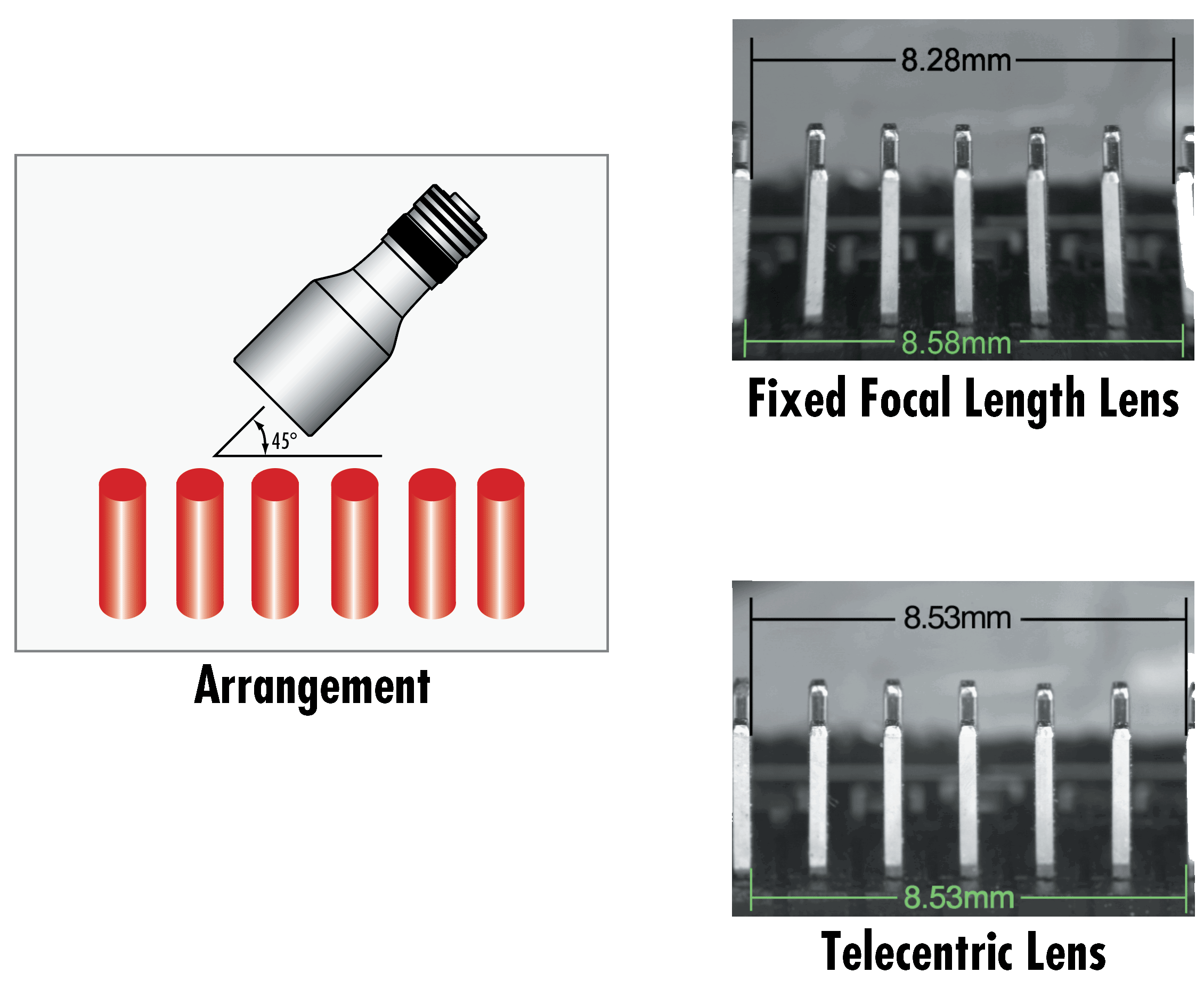
Figure 1: Comparison of jumpers on a circuit board. Figure 1a shows an image that has been taken with a fixed focal length lens. Figure 1b shows an image that has been taken with a telecentric lens. Note that the pins do not appear bent in the telecentric image.
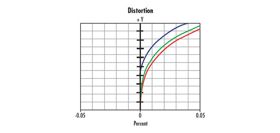
Because telecentric lenses tend to have such low distortion, they are more prone to having non-monotonic wave/mustache distortion than fixed focal length lenses, as shown in Figure 2. While the magnitude of the distortion is generally low enough to not have a significant impact on the measurement of the part under inspection, it is still important to check the distortion specifications of the telecentric lens and to properly calibrate the imaging system utilizing the telecentric lens. This property is also why distortion plots should be used rather than a single numerical value, as the lens can have zero distortion at the field point where it is specified but be non-zero elsewhere.
The distortion of telecentric lenses can be specified in two different ways: TV distortion or geometric distortion. Both are generally classified as a percentage value, but TV distortion values will almost always be lower than geometric distortion values, which can be misleading. When a telecentric lens is specified with geometric distortion values, the value that is given is at the maximum field height of the maximum sensor size that the lens is capable of. In the case where the lens has monotonic distortion, the value that is specified will be the highest. However, in the case of wave distortion, it is important to look at the plot (as in Figure 2) to determine how the distortion is characterized.
The other relevant specification is telecentricity, which is generally specified in degrees, and can be thought of as the residual angular field of view of the lens. Unfortunately, just as no lens has zero distortion, no lens is perfectly telecentric. Figure 3 shows a plot of the telecentricity for a 1X telecentric lens.
The plot in Figure 3 shows three different lines, each representing the telecentricity at different wavelengths (red, green, and blue). The most important nuance to note about the plot is that the telecentricity varies with wavelength, meaning that the accuracy of a measured part can change depending on the wavelength (color) of light that is used to inspect the part. While this variance is small in an absolute sense, it is important to consider when designing systems that require the highest possible accuracy. For these systems, it is best to use monochromatic illumination, preferably the wavelength where the telecentricity was optimized in the design process. Learn more about using proper illumination.
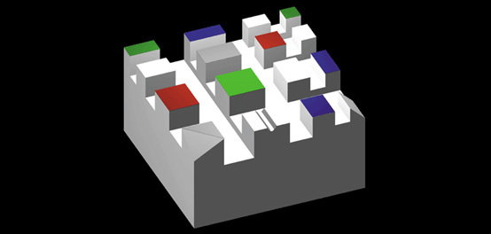
In applications where the object plane is tilted, telecentric lenses provide a good alternative to fixed focal length lenses due to their low distortion and invariant magnification. The camera can also be tilted to keep the tilted object in sharp focus; this is called the Scheimpflug condition. The Scheimpflug condition is a way to extend the depth that is being observed by the machine vision system by tilting the object plane and the image plane, as shown in Figure 4. If a conventional lens is used this way, it will result in keystone distortion, for more information see Distortion. telecentric lenses, however, will not demonstrate keystone distortion, as the magnification does not change with depth. Care must be taken in calibration, though, as the part will be observed as a geometric projection: a circle will be an ellipse, a square will be a rectangle, and so on.


Figure 2: Comparison of monotonic distortion (a) with nonmonotonic, or wave distortion, typical of telecentric lenses (b).

Figure 3: A telecentricity plot for a typical telecentric lens.


or view regional numbers
QUOTE TOOL
enter stock numbers to begin
Copyright 2025 | Edmund Optics BV, De Maas 22B, 5684 PL Best, The Netherlands
California Consumer Privacy Acts (CCPA): Do Not Sell or Share My Personal Information
California Transparency in Supply Chains Act
This content may include material that has been generated or modified using artificial intelligence (AI).
The FUTURE Depends On Optics®