


Optics Application Examples
Application 1: Detector Systems | Application 2: Selecting the Right Lens | Application 3: Building a Projection System
Application 1: Detector Systems
Every optical system requires some sort of preliminary design. Getting started with the design is often the most intimidating step, but identifying several important specifications of the system will help establish an initial plan. The following questions will illustrate the process of designing a simple detector or emitter system.
Goal: Where Will the Light Go?
Although simple lenses are often used in imaging applications, in many cases their goal is to project light from one point to another within a system. Nearly all emitters, detectors, lasers, and fiber optics require a lens for this type of light manipulation. Before determining which type of system to design, an important question to answer is "Where will the light go?" If the goal of the design is to get all incident light to fill a detector, with as few aberrations as possible, then a simple singlet lens, such as a plano-convex (PCX) lens or double-convex (DCX) lens, can be used.

Figure 1: PCX Lens as FOV Limit in Detector Application
Figure 1 shows a PCX lens, along with several important specifications: Diameter of the lens (D1) and Focal Length (f). Figure 1 also illustrates how the diameter of the detector limits the Field of View (FOV) of the system, as shown by the approximation for Full Field of View (FFOV):
Or, by the exact equation:
For detectors used in scanning systems, the important measure is the Instantaneous Field of View (IFOV), which is the angle subtended by the detector at any instant during scanning.
Figure 2: Instantaneous FOV

Figure 3: PCX Lens as FOV Limit in Emitter Application
Considered in reverse, Figure 1 can also represent an emitting system (Figure 3), with the lens used to collimate the light. This setup will be the premise of the application example.
Light Transmission: How Much Light Exists Initially?
Knowing where the light will go is only the first step in designing a light-projecting system; it is just as important to know how much light is transmitted from the object, or the source. The efficiency is based on how much light is received by the detector, thereby answering the question "How much light exists initially?" The Numerical Aperture (NA) and f-number (f/#) of a lens measure the amount of light it can collect based on f, D, index of refraction (n), and Acceptance Angle (θ). Figure 4 illustrates the relationship between f/# and NA.
Figure 4: DCX Lens Showing f/# and NA
Correspondingly, this relationship can be mathematically expressed according to Equation 1.5. It is important to note that the larger the Diameter, the smaller the f/#; this allows more light to enter the system. To create the most efficient system, it is best to match the emitted cone of light from the source to the acceptance cone of the lens, as this avoids over or under filling the lens area.
Optical Throughput: How Much Light gets through the System?
When using a lens as a tool to transfer light from an emitter to a detector, it is important to consider Throughput (TP), a quantitative measurement of transmitted light energy. In other words, answering the question "How much light gets through the system?" dictates the geometry of the lens used and the configuration of the system. Because emitters and detectors are areas of light and not point sources, the diameter of a lens affects TP even when the ratio between Diameter and Focal Length (specified by f/#) remains constant.
Figure 5 shows the basic definition of throughput (TP) as expressed in Equation 1.7, where A is the Area of the object, (light source), Ω is the Solid Angle, and z is the Object Distance (with their conjugates in image space as A', Ω', and z').
Figure 5: DCX Lens Illustrating Throughput
Solid angle is defined as Ω = A/r2, with the area of the lens surface and the radius (r) being the distance from the lens to the object (z) or image plane (z'), for Ω or Ω', respectively.
The amount of light reaching the detector can be reduced by vignetting, which is the result of light being physically blocked within the system due to lens aperture limitations. However, some systems benefit from intentional vignetting, as it can eliminate stray light that would negatively affect the quality of the image. It is important to note that properly aligning the system reduces stray light and unintentional vignetting.
Aberrations: How Does the Image Look?
Determining how much light passes through the system is important, but aberrations within the system also play a major role. Answering "How does the image look?" can lead to improving the system's design in order to reduce aberrations and improve image quality. Aberrations are errors inherent with any optical system, regardless of fabrication or alignment. Since every optical system contains aberrations, balancing performance with cost is an important decision for any designer. Several basic aberrations, such as coma (variation in magnification or image size with aperture), spherical (light rays focusing in front of or behind paraxial focus), and astigmatism (having one focus point for horizontal rays and another for vertical) can be reduced by a large f/#, as shown in the following relations.
Application Example: Detector System
As an example, consider a system in which light is emitted from a ¼" diameter fiber optic light guide, as shown in Figure 3.
- Initial Parameters
NA of Light Guide = 0.55
Diameter of Source (Emitter) = 6.35mm
Index of Refraction of Air = 1 - Calculated Parameters
F- Number (f/#)
A PCX lens of f/1, meaning the f/# is 1, would be ideal to place in front of the light guide in order to collimate as much light as possible. According to Equation 1.4, if the f/# is 1, then the diameter and focal length of a lens are equal. In other words, if we consider a lens with a diameter of 12mm, then the focal length is also 12mm.
Full Field of View (FFOV)
Steradians correspond to a 2-dimensional angle in 3-dimensional space, as the angle from the edge to edge of the lens is in two dimensions. A higher value in steradians is given by a shorter distance from emitter to lens, or a larger diameter of the lens. The largest value a solid angle can have is 4π, or about 12.57, as this would be equivalent to the solid angle of all space.
In order to calculate Throughput (TP) of this system, we need to first calculate the Area of the Source (Equation 1.11), the Area of the Lens (Equation 1.12) and the Solid Angle (Equation 1.13). As a rule of thumb for collimating light from a divergent source (i.e. the light guide in this example), place the lens a distance equal to one focal length away from the source.
Since the system is in free space, where n is approximated as 1, n2 does not factor into the final calculation.
Application 2: Selecting the Right Lens
High image quality is synonymous with low aberrations. As a result, designers often utilize two or more lens elements in order to obtain higher image quality compared to a single lens solution. Many factors contribute to selecting the right lens for an application: type of source, space constraints, cost, etc.
Figures 6a - 6e compare a variety of lens systems for a relay lens, or 1:1 imaging, application. In this specific example, outlined in the following series of comparisons, it is easy to see how image quality is affected by the inherent geometry and optical properties of the lenses chosen.
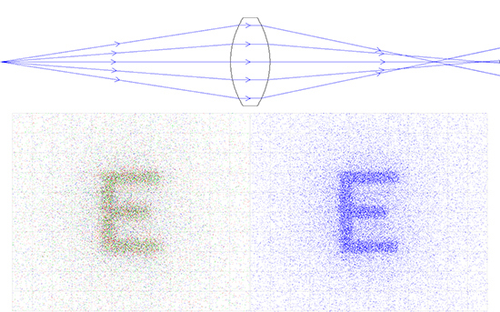
Figure 6a: DCX Lens Relay System: 25mm EFL x 20mm Entrance Pupil Diameter (Left is Color and Right is Monochromatic)

Figure 6b: PCX Lens Relay System: 50mm EFL x 20mm Entrance Pupil Diameter (Left is Color and Right is Monochromatic)
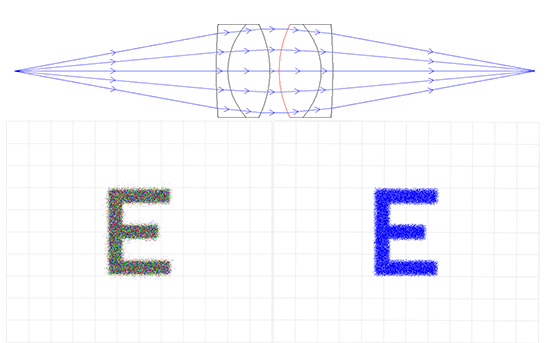
Figure 6c: Achromatic Lens Relay System: 50mm EFL x 20mm Entrance Pupil Diameter (Left is Color and Right is Monochromatic)
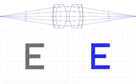
Figure 6d: Aspherized Achromatic Lens Relay System: 50mm EFL x 50mm Entrance Pupil Diameter (Left is Color and Right is Monochromatic)
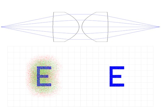
Figure 6e: Aspheric Lens Relay System: 50mm EFL x 40mm Entrance Pupil Diameter (Left is Color and Right is Monochromatic)
Application Example: Single Element Lens System
A double-convex (DCX) lens is regarded as the best single element for 1:1 imaging because of its symmetrical shape, as both sides of the lens have equal power, instead of one side bending rays more than the other, such as a plano-convex (PCX) lens. Since the lens system is made of just one lens, the aperture stop is essentially the lens, which allows for the reduction of many aberrations. For these reasons, a DCX lens is preferable to a single PCX lens for 1:1 imaging. However, it is important to keep in mind that at a low f/#, there is still significant spherical aberration and coma. These aberrations are caused by the Shape Factor (S) of the single lens:
where R1 and R2 are the radii of each surface of the lens.
For applications that only need one lens, with the object or source at infinity, a better shape factor can be found, to reduce whichever aberration is most detrimental to the system. For example, to reduce spherical aberration, the ideal shape factor can be calculated by:
Where n is the Index of Refraction of the Glass Substrate, p is the Position Factor, z is Object Distance (measured to be a negative value), and z' is Image Distance (measured to be a positive value).
To reduce coma for an object at infinity, the Shape Factor can be calculated by:
For glass that has an index of 1.5 (N-BK7 is 1.517), with an object at infinity, a Shape Factor of about 0.8 will balance the corrections of both coma and spherical aberrations.
Application Example: Double Element Lens System
In order to improve the system, a single DCX lens could be replaced with two equal PCX lenses each with a focal length twice that of the DCX, with an aperture stop in the center. Doing so splits the power of each surface of the lenses, as the focal length is inversely proportional to power. Since each lens has less power, there is less spherical aberration created in the system. By using two lenses, the powers of each surface add, which allows for the same overall focal length, but less spherical aberration. Since the diameter also has remained the same, the f/# did not change between using a single DCX or two PCX lenses, but the spherical aberration is decreased, even if the f/# is large.
The convex surfaces are nearly in contact, with the aperture stop located between them. Better image quality is achieved by orienting the convex surfaces towards the longest conjugate distance.
Application Example: Achromatic Lens System
Another option is to use two achromatic lenses, or achromats. An achromatic lens consists of two optical components cemented together, usually a positive low-index (crown) element and a negative high-index (flint) element. Using achromats improves polychromatic (white light, multiple wavelength) imaging as well as reduces spherical aberration and coma. If both lenses are achromats with convex surfaces facing each other, a far superior imaging system is obtained, as many aberrations are significantly reduced compared to the same system with single lenses (either DCX or two PCXs). While spherical aberration is negligible at large apertures or high f/#s, chromatic aberration is greatly reduced with the use of achromats. Many relay lens systems on the market utilize this type of four element configuration.
For more information about the benefits of using achromatic lenses compared to singlet lenses, view Why Use an Achromatic Lens?.
Application Example: Aspheric Lens System
Unlike PCX, DCX and achromatic lenses, which are made from portions of a sphere, an aspheric lens is one that has a curvature other than that of a sphere or cylinder, usually made from portions of a hyperbola or parabola. The key concept of aspheric lenses, or aspheres, is that the radius of curvature varies radially from the optical axis of the lens. As a result, aspheric lenses easily correct spherical aberration, and are great for correcting off-axis aberrations.
Aspheric lenses are used in many systems, as one aspheric lens can replace two or more spherical lenses, thereby reducing space and costs within a system. For more information on the manufacturing, design, and use of aspheric lenses, view All About Aspheric Lenses.
| Type of Lens System | Spherical Aberration | Chromatic Aberration |
|---|---|---|
| DCX Singlet | High | High |
| 2 PCX | Medium | High |
| 2 Achromats | Low | Negligible |
| 2 Aspherized Achromats | Negligible | Negligible |
Application 3: Building a Projection System
Designing a custom projector system can often be time-consuming and expensive. Nevertheless, there are some simple steps to follow to make the process easy and cost-effective. These same basic steps can be applied to many system design applications.
Custom Design Steps:
- Divide the System into Parts – Optical applications are many and varied, from simple magnifiers to laser beam conditioning. Most applications, however, can be broken down into smaller modules that can be developed almost independently.
- Design Each Part Separately – By taking each module and designing it for optimum individual performance, the system as a whole can benefit. This is true as long as the optimization of one module doesn't adversely affect the design of another module, so it is important to keep the overall system in mind as you design the separate parts.
- Computer Optimize – After computing the initial dimensions, putting the design into lens design software, such as ZEMAX or Code V, is the best way to optimize the modules independently, as well as the overall design. Optimizing each system module will give the best case scenarios for which appropriate mounting components can be chosen. This also works as a double check to make sure the calculations yield reasonable data.
- Assemble the System – After each module is designed, the entire system must be constructed. Prior to putting the modules together, it is necessary to check them individually to guarantee they work properly before adding them to the system. After the system is constructed, it is best to run the entire system through lens design software as well, in order to make sure the modules work together correctly within the system.
- Select Parts – Most lens design software packages include a library of stock lens prescriptions and a "closest-match" algorithm, which helps one pick real lenses and items in place of custom parts. Lens design software will optimize to a glass number that may not exist, but the closest-match will yield a very similar glass type that can be purchased. Beyond selecting the right glasses, finding mechanics to fit the system is an important step. Size, weight, and appearance must be considered before choosing lens holders and system mounting.
For more information on glass selection, view Optical Glass.
Most projectors, like the old-fashioned slide projector, employ two main modules: a condenser lens system and a projector lens system. The condenser lens system evenly illuminates a slide; the projector lens system projects an image of the slide onto a screen. Each module can be created with simple components and methods. 25mm diameter optics will be used in this example because of their large aperture and wide variety of focal lengths available.
Part 1: The Projection Lens System
The projection lens system is limited by the desired magnification and throw distance of the reticle image. Since most projection systems utilize white light, using achromatic lenses will yield the best image. To determine which achromats to use, decide how far from the projected image the projection lens system will be (I) and the desired magnification (M). Magnification can be calculated by the focal lengths of the lenses (Equation 3.1) or by the image to object distance (Equation 3.2).
Part 2: The Condenser Lens System
The condenser lens systems collects light from divergent illumination sources, then redirects and condenses the light to flood the projector lens system. The classical condenser lens system consists of two PCX lenses mounted with their convex sides facing each other, as shown in Figure 7. The first lens collects the divergent light cone from the illuminator (object or projector) and the second lens outputs the light as a convergent cone (image), which will illuminate the reticle.
Figure 7: Basic Projection System
Implicitly, the projection lens solution defines part of the condenser lens system, which is why designing the projection lens system first is crucial. The distance of the condenser lens system to the projector lens system is at least as great as the distance from the reticle to the projector lens system.
Application Example: Designing a Projection System
- Initial Parameters
Diameter of Lens = 25mm
Image Distance = Throw Distance = 250mm
Magnification = 2.5X - Calculated Parameters
Object Distance, or Distance to the Reticle
Two 100mm focal length achromatic lenses with a 25mm diameter would be ideal for creating the projection lens system. 25mm diameter lenses are great for their large apertures and compatibility with mechanical components, as well as their variety of coatings and focal lengths.
Focal Length of PCX Condenser Lens
Two 250mm focal length PCX lenses with a 25mm diameter are needed to complete the projection system.


or view regional numbers
QUOTE TOOL
enter stock numbers to begin
Copyright 2025 | Edmund Optics BV, De Maas 22B, 5684 PL Best, The Netherlands
California Consumer Privacy Acts (CCPA): Do Not Sell or Share My Personal Information
California Transparency in Supply Chains Act
This content may include material that has been generated or modified using artificial intelligence (AI).
The FUTURE Depends On Optics®