


Light Sheet Microscopy
Authors: Maura Francis, Cory Boone, Jaclyn Wycoff
Light sheet fluorescence microscopy (LSFM, also known as selective plane illumination microscopy (SPIM), is a medium-to-high-resolution fluorescence microscopy method that captures images at high speeds. It is well-suited for imaging three-dimensional biological samples at multiple depths, known as optical sectioning. A laser light sheet is focused into a two-dimensional plane, typically with a cylinder lens, to illuminate only a thin slice of the sample and excite fluorescence, reducing phototoxicity and damage to the sample (Figure 1).

Figure 1: Light sheet fluorescence microscopy (LSFM) excites fluorescence in three-dimensional samples across a two-dimensional plane that covers a smaller volume than the excitation in conventional fluorescence techniques. This reduces phototoxicity and damage to sensitive biological samples.1
A much larger region of the sample is illuminated in conventional epifluorescence microscopy. The excitation illumination goes through the sample in the axial (z) direction and excites fluorescence both in the focus plane and outside of it.1 This out-of-focus fluorescence makes it more difficult to accurately measure the in-focus signal.
How It Works
In epifluorescence or confocal microscopes, the illumination for excitation and the imaging objective share a common light path. In LSFM, the illumination source is separated and typically perpendicular to the detection path in the system.2 The different LSFM configurations can generally be broken up as systems with either planar or scanned light sheets.1 This guide will primarily discuss the planar light sheet configuration, where a planar laser light sheet is created by the combination of a cylindrical lens paired with a Gaussian beam.2 By flattening the beam traveling through the system, which is otherwise circular, the cylindrical lens creates a sliver of light parallel to the focal plane.2 Since a whole plane is captured, the imaging time is significantly reduced compared to conventional techniques where only a point of light is focused. This is one major disadvantage of the multiphoton microscopy approach, where samples may need to be imaged for hours compared to minutes with LSFM.2 However, data handling and processing quickly become an issue with the amount of data acquired.1 LSFM can be implemented with multiphoton miscopy to improve imaging depths in the specimen and improve spatial resolution.3 Another drawback of LSFM is the complexity of alignment with adopting more than two objectives.
LSFM is primarily used to image biological samples and can be done in vivo. Relatively large (several mm in size), optically-transparent specimens can be imaged using this technique due to the light penetration of the laser sheet. While other techniques may be more attractive to image at higher resolutions, LSFM offers the advantage of low photodamage in a sample. In cell applications where movement and dynamic processes are present, LSFM offers the ability to image large areas quickly.3 This technique can be used to view time-lapse observations in three-dimensional volumes over long periods of time.4 Optical stability must be maintained to get successful time-lapse results. Temperature fluctuations can cause shifts in the sample, and time-lapses are not well-suited for imaging live samples, since they may move as the time-lapse is captured.
The main benefits of light sheet microscopy can all be attributed to its planar illumination. With conventional microscopy techniques, it is difficult to preserve the intensity of the light through the entirety of thick samples. When imaging thick specimens, it is normal to observe light fall off as the light intensity decreases along the length of the focal plane. This can be even more apparent in specimens with opaque features that can block the light. When this happens, there is a striping effect that makes the feature look like it has a shadow, along with a loss of resolution.1 LSFM and the implementation of two illumination sources on either side of the sample help compensate for light falloff.2
Image Appearance
Figure 2, below, shows how the difference in illumination methods between conventional fluoroscence microscopy and LSFM can alter image appearance.
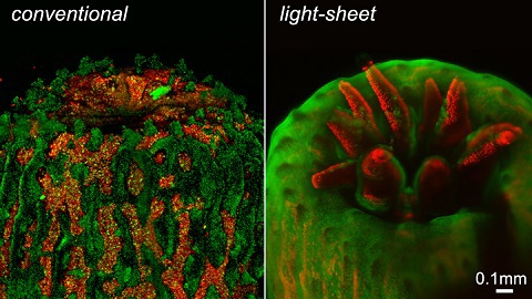
Figure 2: A polyp imaged using a conventional fluorescence microscope contains significant background noise from fluorescence out of the focus plane. The intense illumination also causes the polyp to retract. On the other hand, LSFM eliminates this out-of-focus fluorescence and the polyp fully emerges under the gentler illumination of an LSFM system developed by the University of Essex.1, 4
Figure 2: A polyp imaged using a conventional fluorescence microscope contains significant background noise from fluorescence out of the focus plane. The intense illumination also causes the polyp to retract. On the other hand, LSFM eliminates this out-of-focus fluorescence and the polyp fully emerges under the gentler illumination of an LSFM system developed by the University of Essex.1, 4
There are multiple components of LSFM that play a role in increasing image quality. The sample is translated and rotated to image multiple thin slices parallel to the focal plane, or the light sheet itself is scanned across the sample.2 By capturing the same portion of the sample from different viewing angles, resolution can be increased with the fusion of those separate images. The numerical aperature (NA) of the illumination objectives also influence the resolution.2 The NA dictates the angle that the objective can collect or emit light. An objective with a high NA can achieve better diffraction-limited resolution and causes the visible area of the sample, known as the field of view (FOV), to decrease. However, a small FOV is not ideal for imaging thick specimens because it will take more time to image a given area. LSFM has the ability to image specimens tens of millimeters thick without image degradation from illumination fall off, which is about 9mm thicker than that of a typical confocal microscope.1 This is significant for imaging thick specimens with fluorescence microscopy due to secondary fluorescence occuring outside of the focus region, which can obscure the image. LSFM does not encounter this problem since it only illuminates the plane in focus and no other excess fluorescence gets excited.
When the technique implements a light sheet created by a Gaussian beam with a thin waist, it results in higher resolution in the axial direction. However, it decreases propogation length across the illumination axis. This causes the FOV to be smaller. On the other hand, a Gaussian beam with a thick waist can be used and will result in a longer propogration length but in turn will decrease resolution.4 However, this can also lead to an increase in photodamage to the sample.
Technical Details
While there can be many variations of LSFM setups, Figure 3 shows a typical system layout in which one laser source is used for illumination and a scanning mirror moves the laser beam across a stationary sample. Multiple laser sources and detectors can be incorporated by using dichroic filters, also referred to as dichroic mirrors, to combine the beams.

Figure 3: Simplified schematic for an LSFM system.5
- The Laser Excitation Source: emits a Gaussian laser beam into the system to focus onto the sample. Multiple lasers may be combined using dichroic filters and all directed onto the scanning mirror.3
- Scanning Mirror: adjusts the position of the laser beam and determines where it contacts the sample.
- Beam Expander: increases beam diameter before it reaches the cylinder lens. This allows for a tighter focus in the narrow dimension of the light sheet.
- Cylinder Lens: focuses the beam in one dimension so that a thin light sheet is formed at the sample after the beam passes through the illumination objective.
- Illumination Objective(s): placed perpendicular to the detector(s). It determines the FOV and amount of light the sample is exposed to depending on its NA. Two illumination objectives and laser beam paths are sometimes used on either side of the sample to minimize light falloff.
- Sample Mounting: critical because it essentially determines what LSFM to implement. Different forms of securing a sample can be done by immobilizing it in a gel, hooking it, immersing it in a medium, or placing it on a coverslip.2
- Detector Objective(s): collects the light that propagates out of the system for it to get analyzed. High NA's are typically preferred to improve resolution, and water immersion objectives are often used when the sample is immersed in a liquid.
- Filters: notch, longpass, or bandpass filters eliminate any of the laser illumination that may be scattering off of the sample.
- Tube Lens: forms an image on the detector. When using multiple detectors, dichroic filters may split up the different wavelengths after the detector objective. Each wavelength would then have its own beam path, notch filter, tube lens, and detector.
- Detector: capture images.
- Translation Stage (xyzθ): allows for movement in the x-y-z directions with rotation. This enables images to be captured at different viewing angles which then get fused together to increase resolution.
Applications of Light Sheet Fluorescence Microscopy
Application 1: Tracking Embryogenesis (Embryo Development)
One of the most common use cases of LSFM is tracking the development of embryos in both humans and animals, which is known as embryogenesis.1 Embryos are labeled with fluorescent markers that can be excited by the light sheet of an LSFM system. This allows scientists to track cell growth in developing embryos. Software implementation allows for automated cell tracking. LSFM's large field of view and high speed make it advantageous for imaging embryos and other large, living samples.
Application 2: Otolaryngology (Studying Ears and Hearing)
LSFM has also been an instrumental technique for otolaryngology, as it is well-suited for imaging the components of the middle and inner ear.1 LSFM allowed researchers to generate 3D models of ear structures that were more detailed than past models.
Comparison to Other Microscopy Techniques6
| Technique | Resolution | Sample Size | Relative Cost | Photobleacing |
|---|---|---|---|---|
| Confocal Microscopy | <µm | µm | $$ | Yes |
| Multiphoton Microscopy | <µm | mm | $$$ | Less |
| Light Sheet Fluorescence Microscopy | µm | >cm | $ | Least |
Light Sheet Fluorescence Microscopy at Edmund Optics®
Edmund Optics® supplies a wide range of optics for LSFM applications including beam expanders, cylinder lenses, microscope objectives, and notch filters. Components ideal for these systems are continuously added to keep up with developments in this application space.
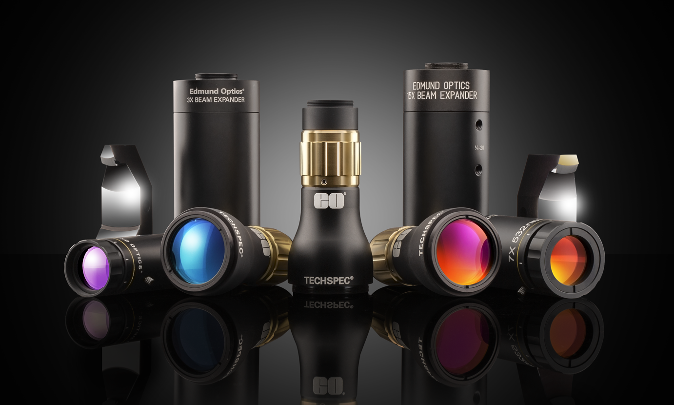
 Beam Expanders
- Used to Expand the Excitation Beam After the Scanning Mirror
- Wide Range of Laser Line and Broadband Coatings from 257nm to 3µm
- Designs with Divergence and Magnification Adjustment Available
- High-Power Assemblies with No Issues from Internally-Focusing Ghost Images
BUY NOW
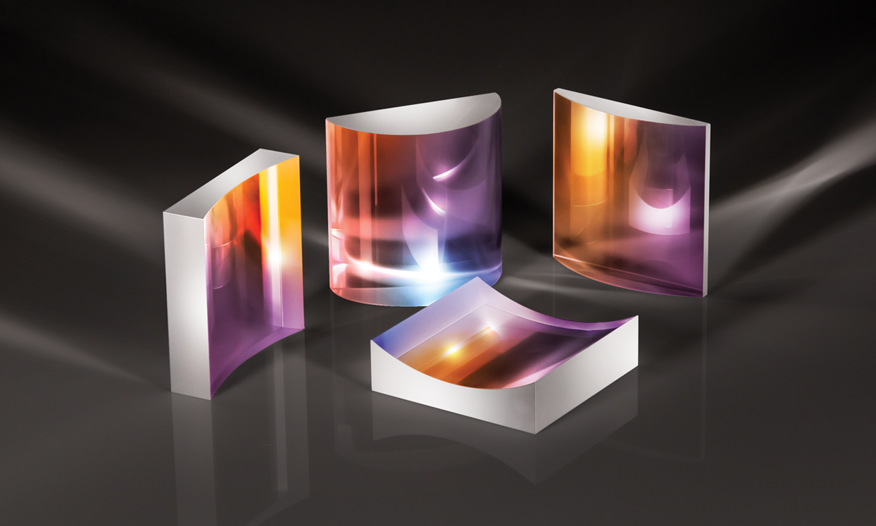
Laser Grade Cylinder Lenses
- Focus Illumination Beam in One Dimension to Form the Light Sheet
- Laser Line and Broadband Coatings for Common Lasers
- Laser Line Coatings Offer <0.25% Reflectivity
- Fused Silica Substrates
BUY NOW
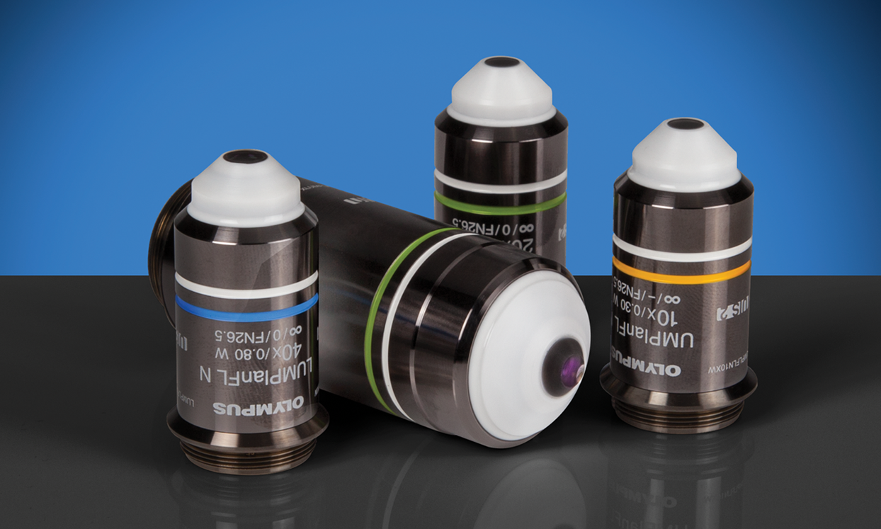
Olympus Water Immersion Objectives
- Magnification Ranges from 10 to 40X
- Display Flat Images from High Transmission Factors up to the Near-Infrared Region of the Spectrum
- Ideal for Fluorescence Imaging of Tissue and Specimens, such as Brain Tissue
BUY NOW

Olympus X-Line Extended Apochromat Objectives
- High Numerical Aperture (NA) up to 1.45
- Chromatic Aberration Correction from 400 - 1000nm
- Uniform Image Flatness over Large FOVs
BUY NOW
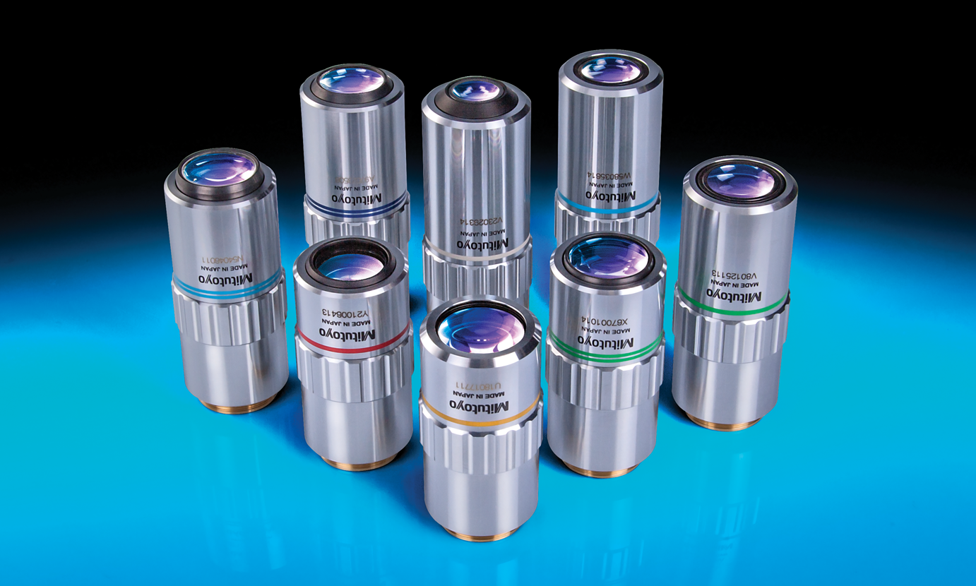
Mitutoyo Infinity Corrected Long Working Distance Objectives
- Bright Field Inspection
- High Quality Plan Apochromat Design
- Flat Image Surface over Entire Field of View
BUY NOW
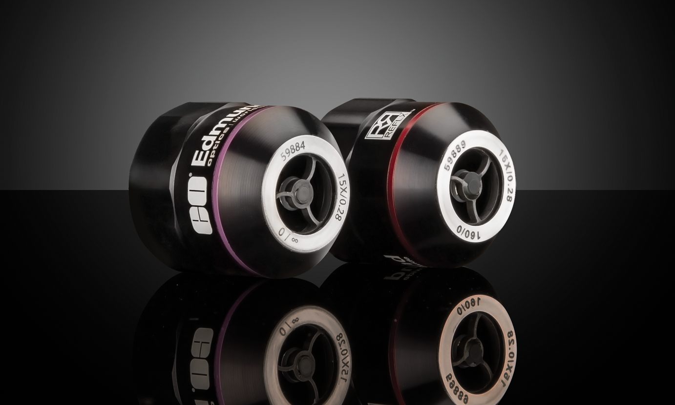
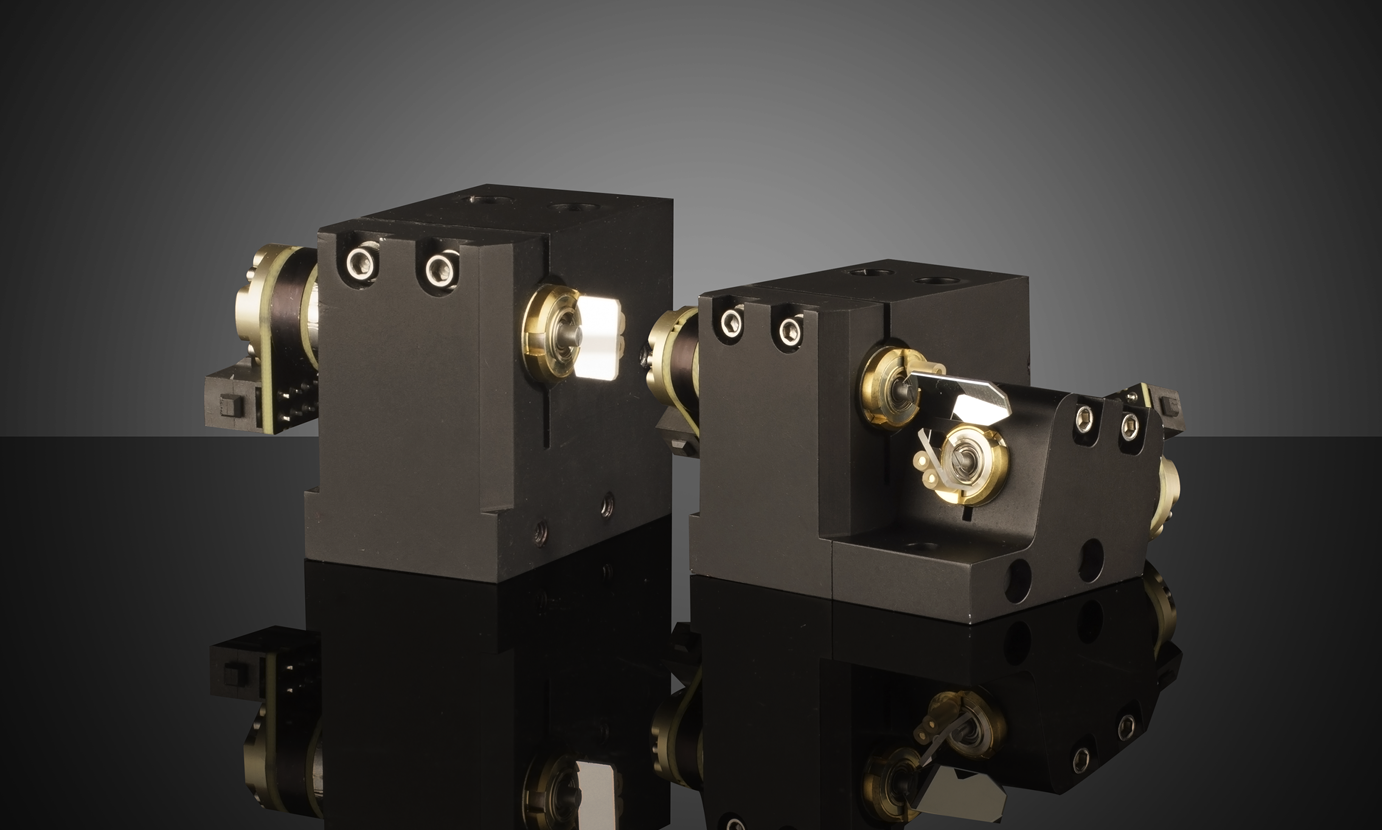
Reflective Objectives
- Long Working Distance for Simple System Integration
- Actively Aligned for Optimal Performance
- Ultra-Wide Spectral Band from 190nm to 11μm with No Chromatic Aberration
- Diffraction-Limited Options with Transmitted Wavefront of λ/14 RMS
BUY NOW
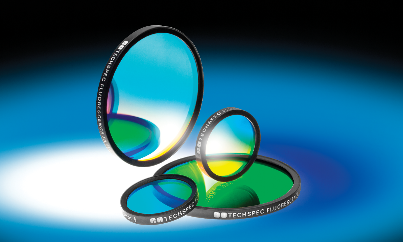
Fluorescence Bandpass Filters
- Common Wavelengths for Popular Fluorophores
- Excitation Filters and Emission Filters Available
- >93% Transmission
- >OD 6 Blocking, <3% from Edge of Bandwidth
- Fluorescence Filter Sets and Pre-Mounted Fluorescence Filter Cube Sets Also Available
BUY NOW
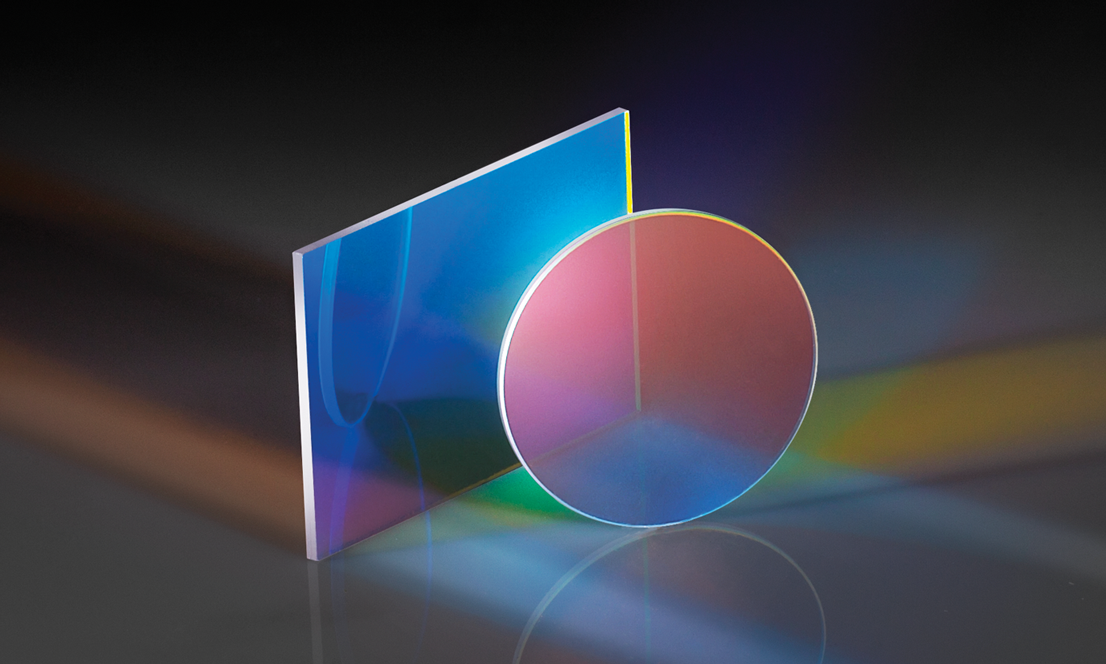
Fluorescence Dichroic Filters
- Ideal for Fluorescence or Multispectral Imaging
- Sharp Transition from Reflection to Transmission
- Extended Reflection and Transmission Bands
- High Performance Fluorescence Dichroic Filters are Also Available
BUY NOW
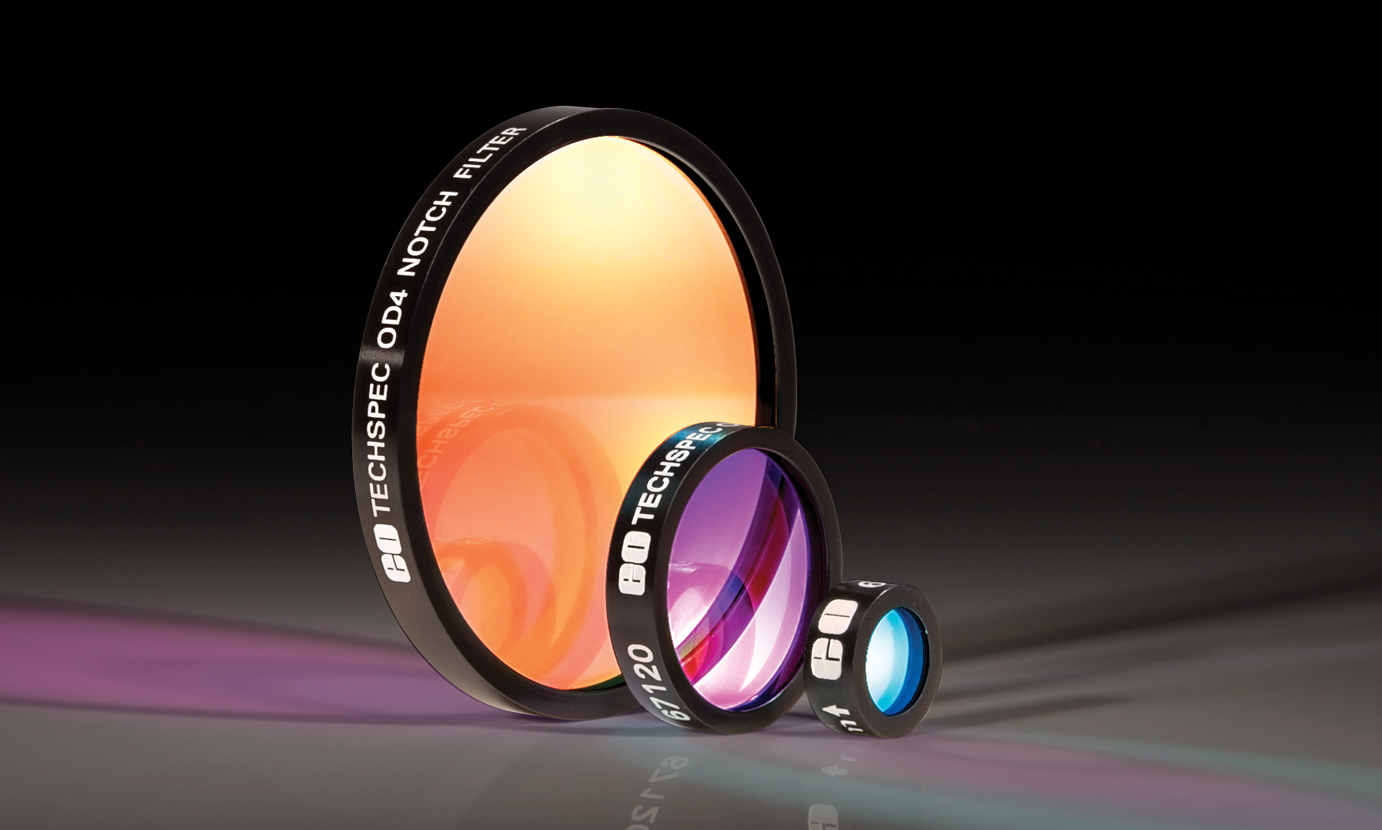
Notch Filters
- Block Any Excitation Wavelengths that may Scatter Off Sample
- OD 4.0 and OD 6.0 Options
- Broad Transmission Ranges
BUY NOW
ScannerMAX Saturn Galvanometer Optical Scanners
- 3, 5, and 10mm Mirror Apertures
- Single Axis and Dual Axis Configurations
- High Performance Scanners for Imaging and Projection Applications
BUY NOW
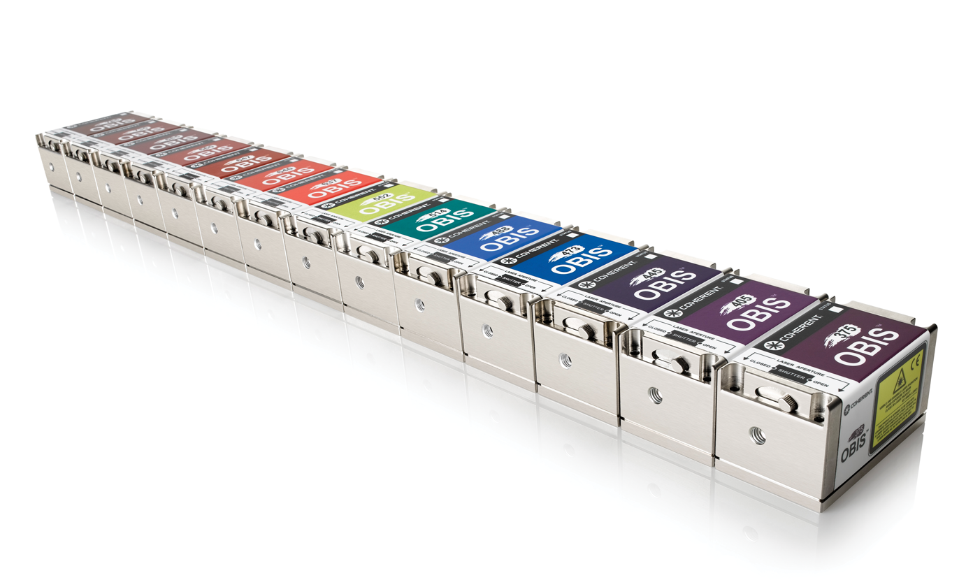
Coherent® High Performance OBIS™ LX/LS Laser Systems
- Same Compact Design for All Wavelength Options
- Integrated Control Electronics with Analog and Digital Modulation
- Circular Beam with Superior Beam Quality
- Coherent® High Performance OBIS™ LX/LS Fiber-Pigtailed Laser Systems Also Available
BUY NOW

Dovetail Optical Rail Systems
- Wide Range of Carrier Length and Mounting Hole Options Available
- Low Profile Design with Smooth Movement
- Increased Stability and <1mrad Straight Line Accuracy
BUY NOW
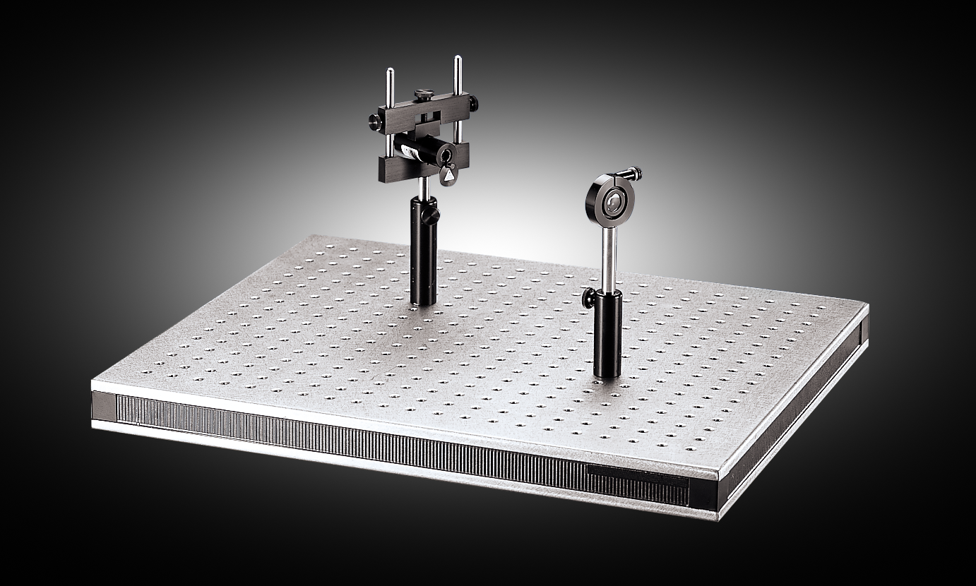
Optical Tables and Breadboards
- Bench Plates, Composite Breadboards, and Laboratory Tables
- English and Metric Options
- Variety of Breadboard Accessories and Optomechanics Available
BUY NOW
References
- Allen, J. R. “Light Sheet Fluorescence Microscopy.” Nikon, https://www.microscopyu.com/techniques/light-sheet/light-sheet-fluorescence-microscopy
- Pasche-Drews, M. “Application Note: Light Sheet Microscopy.” Teledyne Photometrics, https://www.photometrics.com/applications/appnotes/light-sheet-microscopy.
- Albert-Smet, I. et al. “Applications of Light Sheet Microscopy in Microdevices.” Front. Neuroant. https://www.frontiersin.org/articles/10.3389/fnana.2019.00001/full
- Laissue, P. P., et al. (2017). Assessing phototoxicity in live fluorescence imaging. Nature Methods, 14(7), 657-661. doi: 10.1038/nmeth.4344.
- Olarte, O. E., et al. (2018). Light-sheet microscopy: a tutorial. Advances in Optics and Photonics, 10(1), 111-179. doi.org/10.1364/AOP.10.000111
- Santi, P. A. (2011). Light Sheet Fluorescence Microscopy. J Histochem Cytochem, 59(2), 129-138. doi: 10.1369/0022155410394857
Additional Resources
- Brightfield Illumination Microscopy
- Darkfield Illumination Microscopy
- Confocal Microscopy
- Differential Interference Contrast Microscopy
- Fluorescence Microscopy
- Multiphoton Microscopy
- Phase Contrast Microscopy
- Digital Microscope Objective Setups
- Understanding Microscopes and Objectives
- Considerations When Using Cylinder Lenses
- What Are Cylinder Lenses?
- Gaussian Beam Propagation
- Gaussian Beams Calculator
- Laser Beam Expanders


or view regional numbers
QUOTE TOOL
enter stock numbers to begin
Copyright 2025 | Edmund Optics BV, De Maas 22B, 5684 PL Best, The Netherlands
California Consumer Privacy Acts (CCPA): Do Not Sell or Share My Personal Information
California Transparency in Supply Chains Act
This content may include material that has been generated or modified using artificial intelligence (AI).
The FUTURE Depends On Optics®