


Shape Factor Influence in Aspheric Lens Design
As the availability of aspheric lenses increases, optical system integrators should possess a basic knowledge of the design process to obtain the lens best suited for their needs. An asphere is an optical lens that does not have a constant radius of curvature, thus it is not a portion of a sphere. Aspheric lenses improve performance and can reduce the number of lens elements needed in several applications including laser-enabled devices, cinematography lenses, smartphone cameras, and surgical instruments.
When designing an aspheric lens, it is important to consider the application for which the specific lens is intended, as this will determine the shape factor of the lens. The shape factor of an asphere is a ratio of surface curvatures that describe the shape of the lens and typically ranges from values of -2 to +2 as shown in Figure 1. The sign of the shape factor is based upon the orientation of the lens with respect to the object being imaged. For example, a shape factor of +1 denotes that the convex, or curved, side of the lens faces the object.
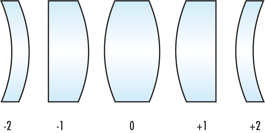
Figure 1: Examples of lenses with varying shape factors.
Most aspheric lenses manufactured by Edmund Optics® fall into two different shape factors and design approaches: "best form" aspheres and "prime" aspheres. Best form aspheric lenses begin with a shape factor of -1, so that the planar side of the lens faces the object. Prime aspheres, on the other hand, use the opposite configuration with the curved surface facing the object and, therefore, have a shape factor of +1 (Figure 2). Lens shape factor directly impacts lens performance, allowing prime aspheres to handle shifts in wavelength and field angle better than best form lens designs.
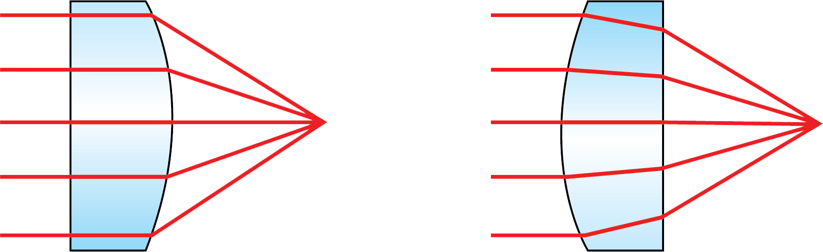
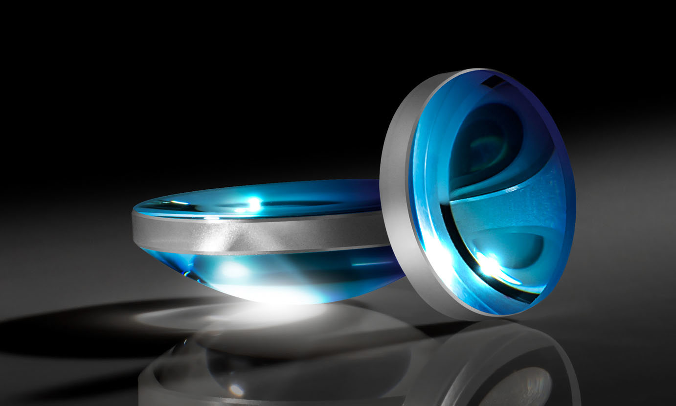
Figure 2: Comparison of the orientations of best form aspheres (left) and prime aspheres (right), which are differentiated by which surface faces the object.
Best Form Aspheric Lenses
Best form aspheric lenses are closed-form solutions, meaning that there is an explicit superior practice for designing these aspheres. While this makes them simpler to design, it also limits their abilities. The curved surface of best form aspheres begins with a base conic constant of -1. The conic constant is found using the equation $ \small{ k = -1 \times n^2} $ where "$ \small{n} $" is the refractive index of the glass or other material used for the lens.
Best form aspheric lenses achieve diffraction-limited focused spots on-axis for a given wavelength, but changing wavelengths result in chromatic aberrations and reduced performance for wavelengths different than the design wavelength. The lens's refractive index and spherical aberration correction vary with wavelength, which is known as spherochromatism. This makes best form aspheres ideal for monochromatic and highly-collimated applications, such as laser systems.
However, the flat surface of the asphere reflects incident light directly back to the source, which could be a cause for concern in certain laser applications. Using an asphere designed for a -1 configuration in a +1 configuration with the collimated source incident on the convex surface will result in poor performance.
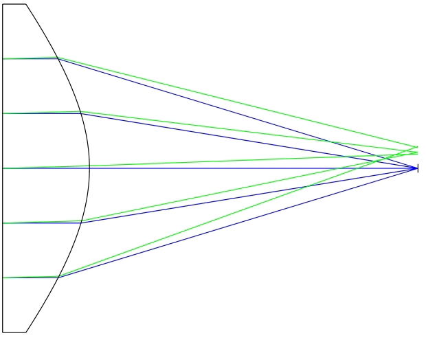
Figure 3: In best form aspheres, all the optical power comes from the curved surface facing the focused spot, leading to several disadvantages for certain situations (e.g. increased spherochromatism) compared to prime aspheres.
Additionally, best form aspheres experience coma when the object or light source strays from the optical axis. This presents itself at small angles, some as small as 0.1 degrees. Therefore, these lenses should only be used in one of two configurations: either with an infinite conjugate source incident on the planar side of the lens or with a point source that is a focal length away from the convex surface.
Prime Aspheric Lenses
Prime aspheric lens designs begin with a base conic of +1 and do not have closed-form solutions. Therefore, the design process is more involved and the even sphere asphere polynomial must be used to determine the surface sag of the desired lens.
Where:
- $ Z $: sag of surface parallel to the optical axis
- $ s $: radial distance from the optical axis
- $ C $: curvature, inverse of radius
- $ k $: conic constant
- $ A_4, \, A_6, \, A_8 \, ... $: 4th, 6th, 8th… order aspheric coefficients
The +1-shape factor of prime lenses denotes the orientation where the convex surface faces the object and in which both surfaces have power to refract incoming rays. While this configuration may be more effective in certain applications, it makes the design process more complex. For prime aspheres, a complication arises for lenses that have f/#’s approaching 1. (For more information on f/#, please see our System Throughput, f/#, and Numerical Aperture application note). When the curvature of a low f/# lens approaches that of a hemisphere, incoming light rays may be refracted at angles such that total internal reflection (TIR) occurs. This is mitigated by adding an arbitrary conic to the lens configuration so that the oblique rays may be corrected to be less than the critical angle.
In the polynomial above, the second and fourth terms are often adjusted to zero in asphere applications, as the second term affects the radius of the lens and the fourth term affects the conic constant. It is important to note that these variable constants depend on the optimization of the lens and the existence of a diffraction-limited spot size. In the case of prime aspheric lenses, the fourth term may vary as it will not affect optimization. Any inflection points in the design could increase the complexity and cost of manufacturing the lens.
A cross-section of the curvature of the aspheric lens’ surface should be taken and examined for inflection points. For more information regarding aspheric lens inflection points please see the SPIE 2012 article “Asphere design for dummies”.1
Comparison of Best Form and Prime Aspheric Lenses
While prime lenses require more time and involvement to design, their advantages over best form lenses are often well worth it. Best form lenses often struggle with spherochromatism and narrow field, as previously mentioned. Figure 4 and Figure 5 show spot size comparisons between both design approaches. Prime design allows for the mitigation of these difficulties. The orientation of prime aspheres allows for smaller spot sizes due to the refracting power being split between two surfaces instead of one. Additionally, this orientation causes prime aspheres to be less sensitive to changes in light wavelength. Finally, prime aspheres are better at handling off-axis rays and misalignment in systems. Off-axis performance is better suited to these lenses than best form designs. However, for all the advantages of prime aspheric lenses, they do have their disadvantages. When their orientation is flipped, performance will deteriorate, and total internal reflection may occur. Thankfully, this is easily avoided by being familiar with the intended design of prime aspheres and recognizing their correct orientation.
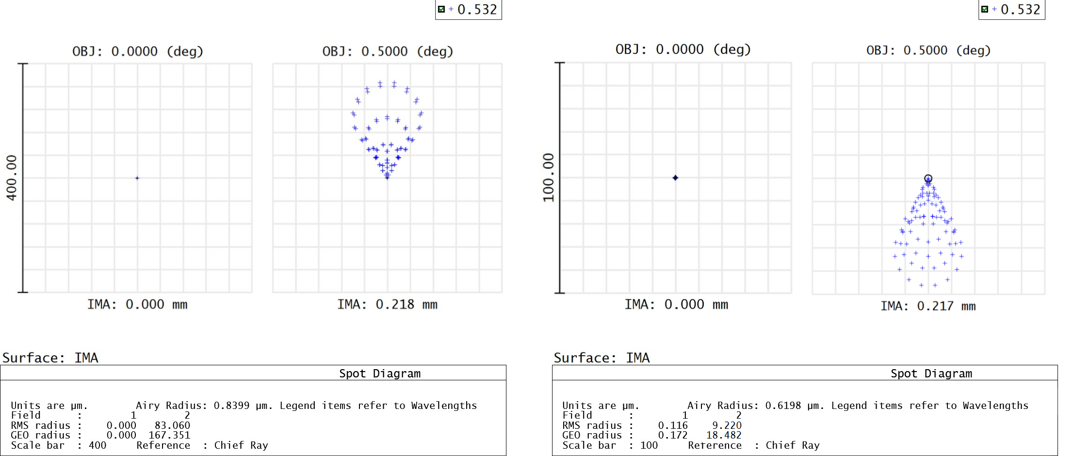
Figure 4: This comparison of spot sizes between a best form asphere (top) and prime asphere (bottom) with both an on-axis field and a 5° field reveals that the prime asphere achieves significantly better off-axis performance (note the difference in scales).
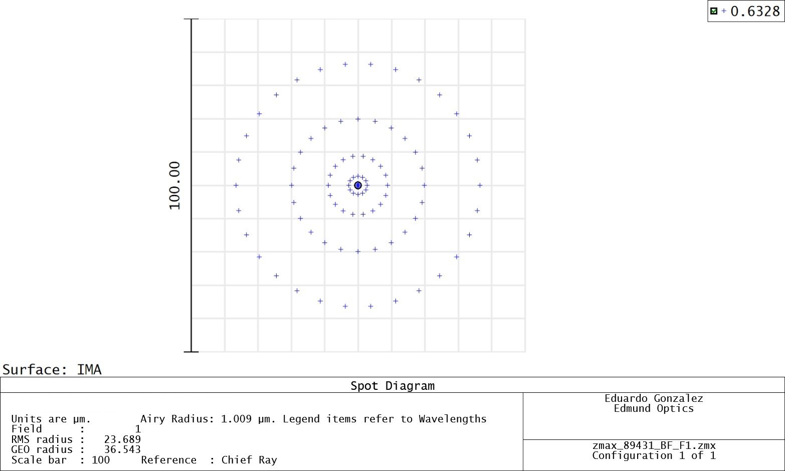
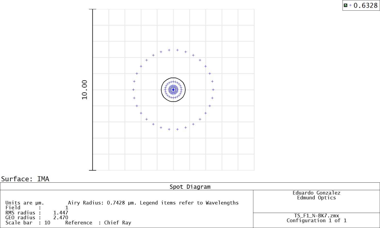
Figure 5: On-axis spot sizes for a best form asphere (top) and prime asphere (bottom) are shown above for 632.8nm, a wavelength shifted away from the design wavelength of 532nm.
Overall, the most important factor in aspheric lens design is open and thorough communication between the designer and manufacturer. This allows for the shape factor and other lens components to be carefully considered so that errors are avoided, and the correct lenses are implemented for every application. Contact us to discuss your application and ensure that you leverage the right optical components to achieve your application goals.
References
- K. Oka and S. Sparrold, “Asphere design for dummies,” Proc. SPIE, 8487, 84870B (Oct. 19, 2012); doi:10.1117/12.930989.
Aspheric Lenses from Edmund Optics®
 Best Form Aspheric Lenses
Best form aspheric lenses are ideal for monochromatic focusing or collimating applications.
BUY NOW
Prime Aspheric Lenses
Prime aspheres are able to better handle shifts in wavelength and field angle than best form aspheres, making them more versatile and beneficial for many applications.


More Resources
- All About Aspheric Lenses
- How an Aspheric Lens is Made Video
- Large Aspheres: Enabling High-Power Optical Systems
- High-End Asphere Design for Manufacturability Webinar Recording
- Aspheric Lens Irregularity and Strehl Ratio
- Aspheric Lens Takeover
- Understanding Optical Lens Geometries
- Metrology at Edmund Optics: Measuring as a Key Component of Manufacturing Video


or view regional numbers
QUOTE TOOL
enter stock numbers to begin
Copyright 2025 | Edmund Optics BV, De Maas 22B, 5684 PL Best, The Netherlands
California Consumer Privacy Acts (CCPA): Do Not Sell or Share My Personal Information
California Transparency in Supply Chains Act
This content may include material that has been generated or modified using artificial intelligence (AI).
The FUTURE Depends On Optics®