


Key Parameters of a Laser System
This is Sections 1.1 and 1.2 of the Laser Optics Resource Guide.
There is a vast range of common laser systems from applications as diverse as materials processing, laser surgery, and remote sensing, but many laser systems share common key parameters. Establishing common terminology for these parameters prevents miscommunication, and understanding them allows for properly specifying laser systems and components to meet your application needs.

Figure 1: Schematic of a common laser materials processing system in which each of the 10 key parameters of a laser system are indicated by their corresponding numbers
Fundamental Parameters
The following fundamental parameters are the most basic concepts of laser systems and are critical for understanding more advanced topics.
1: Wavelength (Typical Units: nm to µm)
A laser’s wavelength describes the spatial frequency of the emitted light wave. The optimal wavelength for a given use case is highly application-dependent. Different materials will have unique wavelength-dependent absorption properties in materials processing, leading to different interactions with the material. Similarly, atmospheric absorption and interference will affect certain wavelengths differently in remote sensing, and various complexions will absorb certain wavelengths differently in medical laser applications. Shorter wavelength lasers and laser optics are advantageous for creating small and precise features with minimal peripheral heating because of a smaller focused spot. However, they typically are more expensive and prone to damage than lasers at longer wavelengths.
2: Power and Energy (Typical Units: W or J)
The power of a laser is measured in watts (W) and is used to describe either the optical power output of a continuous wave (CW) laser or the average power of a pulsed laser. Pulsed lasers are also characterized by their pulse energy, which is directly proportional to average power and inversely proportional to the laser’s repetition rate (Figure 2). Energy is measured in joules (J).
$$ \text{Pulse Energy} = \frac{\text{Average Power}}{\text{Repetition Rate}} $$
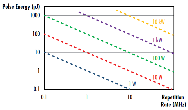
Figure 2: Visual representation of the relationship between pulse energy, repetition rate, and average power for pulsed lasers
Higher power and energy lasers are typically more expensive, and they generate more waste heat. As powers and energy increase, it also becomes increasingly more difficult to maintain high beam quality. More information on pulsed and CW lasers can be found in our Understanding and Specifying LIDT of Laser Components application note.
3: Pulse Duration (Typical Units: fs to ms)
The laser pulse duration, or pulse width, is commonly defined as the full width at half-maximum (FWHM) of the laser’s optical power vs. time (Figure 3). Ultrafast lasers, which have numerous benefits for a range of applications including precise materials processing and medical lasers, are characterized by short pulse durations on the order of picoseconds (10-12 s) to attoseconds (10-18 s). More information can be found in our Ultrafast Dispersion and Highly-Dispersive Mirrors application notes.
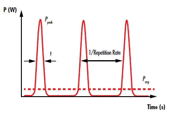
Figure 3: The pulses of a pulsed laser are temporally separated by the inverse of the repetition rate
4: Repetition Rate (Typical Units: Hz to MHz)
A pulsed laser’s repetition rate, or pulse repetition frequency, describes the number of pulses emitted every second, or the inverse temporal pulse spacing (Figure 3). As mentioned earlier, repetition rate is inversely proportional to pulse energy and directly proportional to average power. While repetition rate is often dependent on the laser gain medium, in many cases it can be varied. Higher repetition rates result in less thermal relaxation time at the surfaces of the laser optics and at the final focused spot, which leads to more rapid material heating.
5: Coherence Length (Typical units: mm to m)
Laser light is coherent, meaning that there is a fixed relationship between the electric field phase values at different times or locations. This occurs because laser light is produced by stimulated emission, unlike most other types of light sources. Coherence degrades throughout propagation and the coherence length of a laser defines a distance over which its temporal coherence is maintained to a certain quality.
6: Polarization
Polarization defines the orientation of the electric field of light waves, which is always perpendicular to the direction of propagation. Much of the time, laser light will be linearly polarized, meaning that emitted electric fields consistently point in the same direction. Unpolarized light would have electric fields pointing in many different directions. The degree of polarization is often expressed as a ratio of the optical power of two orthogonal polarization states, such as 100:1 or 500:1. For more information about polarization, visit our Introduction to Polarization application note.
Beam Parameters
The following parameters characterize the shape and quality of laser beams.
7: Beam Diameter (Typical Units: mm to cm)
A laser’s beam diameter characterizes the transverse extension of the beam, or its physical size perpendicular to the direction of propagation. It is often defined at the 1/e2 width, which is bounded by the points where the beam’s intensity reaches 1/e2 (≈ 13.5%) of its maximum value. At the 1/e2 point, the electric field strength drops to 1/e (≈ 37%) of the maximum value. The larger the beam diameter, the larger the optics and the overall system need to be to avoid clipping the beam, which adds cost. However, decreasing beam diameter increases the power/energy density, which can also be detrimental (see next parameter).
8: Power or Energy Density (Typical Units: W/cm2 to MW/cm2 or µJ/cm2 to J/cm2)
Beam diameter is related to the power/energy density, or the optical power/energy per unit area, of a laser beam. The larger the beam diameter, the smaller the power/energy density of a beam of constant power or energy. High power/energy densities are often ideal at the final output of a system (such as in laser cutting or welding), but low power/energy densities are often beneficial inside a system to prevent laser-induced damage. This also prevents high power/energy density regions of the beam from ionizing the air. For these reasons, among others, laser beam expanders are often used to increase the diameter, and thereby decrease the power/energy density inside of a laser system, as described in our Laser Beam Expanders application note. However, care must be taken to not expand a beam so much that it experiences clipping from apertures in the system, leading to wasted energy and potential damage.
9: Beam Profile
A laser’s beam profile describes the distribution intensity at a cross-section of the beam. Common beam profiles include Gaussian and flat top beams, whose beam profiles follow Gaussian and flat top functions, respectively (Figure 4). However, no laser can produce a perfectly Gaussian or perfectly flat top beam whose beam profile matches its characteristic function perfectly, as there is always some amount of hotspots or fluctuations inside a laser. The difference between a laser’s actual beam profile and that of an ideal beam is often described through metrics including a laser’s M2 factor. More information about beam profiles and characterizing beam quality can be found in our Gaussian Beam Propagation and Beam Shape, Beam Quality, and Strehl Ratio application notes.
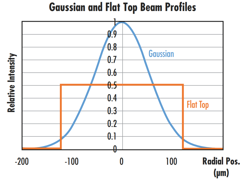
Figure 4: A comparison of the beam profiles of Gaussian and flat top beams with the same average power or intensity shows that the Gaussian beam will have a peak intensity 2X that of the flat top beam
10: Divergence (Typical Units: mrad)
While laser beams are often assumed to be collimated, they always contain some amount of divergence, which describes how much the beam spreads out over increasing distance from the laser’s beam waist, because of diffraction. Divergence becomes an especially significant issues in applications with a long working distance, such as LIDAR systems where an object may be hundreds of meters away from the laser system. Beam divergence is typically defined by the laser’s half angle, and the divergence (θ) of a Gaussian beam is defined as:
$$ \theta = \frac{\lambda}{\pi w_0} $$
λ is the laser’s wavelength and w0 is the laser’s beam waist. More information about divergence can be found in our Gaussian Beam Propagation application note. Divergence can be decreased by increasing the beam diameter, as described in our Laser Beam Expanders application note.
Final System Parameters
These final parameters describe the performance at the output of laser systems.
11: Spot Size (Typical Units: µm)
The spot size of a focused laser beam describes the beam diameter at the focal point of a focusing lens system. In many applications, such as materials processing and medical surgery, the goal is to minimize spot size. This maximizes power density and allows for the creation of especially fine features (Figure 5). Aspheric lenses are often used instead of conventional spherical lenses to reduce spherical aberrations and produce smaller focal spot sizes. Some types of laser systems do not end in focusing the laser down to a spot, in which case this parameter is not applicable.

Figure 5: Laser micro-machining experiments at the Italian Institute of Technology showed a ten-fold increase in the ablation efficiency of a nanosecond laser drilling system when decreasing the spot size from 220μm to 9μm at constant fluence1
12: Working Distance (Typical Units: µm to m)
The working distance of a laser system is commonly defined as the physical distance from the final optical element (typically a focusing lens) to the object or surface the laser is focusing onto. Certain applications, such as medical lasers, often seek to minimize working distance, while other applications, such as remote sensing, often aim to maximize their working distance range.
References:
Brandi, Fernando, et al. “Very Large Spot Size Effect in Nanosecond Laser Drilling Efficiency of Silicon.” Optics Express, vol. 18, no. 22, 2010, pp. 23488–23494., doi:10.1364/oe.18.023488.


or view regional numbers
QUOTE TOOL
enter stock numbers to begin
Copyright 2025 | Edmund Optics BV, De Maas 22B, 5684 PL Best, The Netherlands
California Consumer Privacy Acts (CCPA): Do Not Sell or Share My Personal Information
California Transparency in Supply Chains Act
This content may include material that has been generated or modified using artificial intelligence (AI).
The FUTURE Depends On Optics®